How can failures in vibration tests be avoided?
- Posted by María Teresa Rodríguez
- On May 16, 2019
- 0
It is easy, anticipate to the problems using simulation tools!
As it has been mentioned in “Vibration Test on Hi-Rel for EEE Parts”, vibration tests are important to check the reliability of the components/assemblies. These tests can be a headache and suppose a great cost if the design of the device and the fixing tool are not properly done. Simulation tools are the key to anticipate the problems reducing costs and lead times and doEEEt gives you access, in just one site, to components and specifications from different systems and space agencies
Introduction to Modal Analysis:
All objects have a natural frequency inherent to each object, at which they vibrate when they are subjected to certain external forces. When a force is applied at the object’s natural frequency, it goes into resonance, and a higher amplitude vibration response is created. This situation can cause a collapse of the object. To avoid resonance, the frequency applied should not be at or near the natural frequency of the device or element under test. If the forcing frequency cannot be changed, natural frequency needs to be modified. This can only be done by altering the mass or its stiffness.
Simulation is used to validate the designs before manufacturing and testing phase in a laboratory. It is really useful to crosscheck the results of this analysis with the results obtained in the validation of the final assembly under the applicable vibration test and avoiding the resonance effect.
Vibration simulation, as others, is based in finite element analysis (FEA). The main goal of a modal analysis is to determinate the natural frequencies and vibration modes of an element during vibration. Usually to develop this type of analysis, Finite Elements Method (FEM) is used.
FEM is a method to solve differential equations and boundary value problems. It involves dividing a whole domain into simpler parts that are called finite elements.
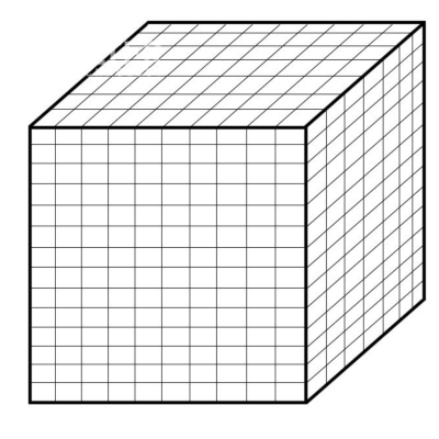
A set of finite elements that make up the model to be simulated is called mesh. The mesh should be as regular and uniform as possible, and the size of the elements will depend on the precision needed to reproduce properly the geometry of the item to simulate. Once the model is ready, simulation tools proceed to the calculation and analysis of the results.

Example of a discretization model in finite elements
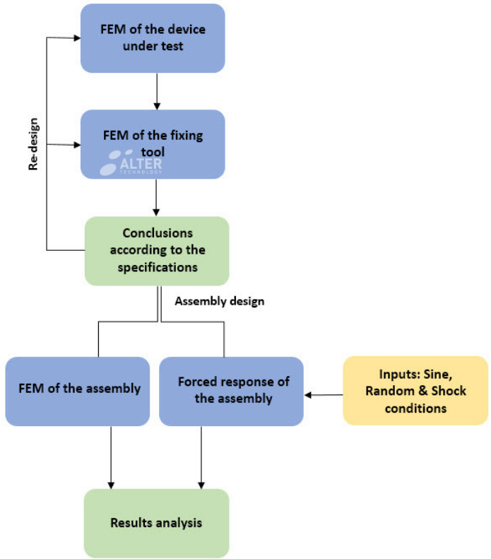
The success relies on the simulation of the natural frequencies of the DUT, the fixing tool and the assembly of both parts. The final simulation consists of the analysis of the forced response of the assembly under the conditions of the requirements. If any of the results fails, a re-design of any of the parts (the device, the fixing tool or the assembly) is required.
Requirements for the Simulation:
To perform all the simulations, the following information needs to be provided:
- Materials and their mechanical properties of the fixing tools and the device under test (DUT). Also the surrounding elements, meaning the fitting interfaces of the tool with the shaker, in order to be able to do a proper model for the MEF analysis and to check with our vibration tool. This point is important because it may cause a big variation of the results due to the variation of the inner dynamics and damping of the DUT and are mainly known as boundary conditions.
- Damping is a very important factor in the simulation. It is the way a system naturally dissipates energy. Its level cannot be studied by FEM. It is usually taken out by a Modal test. It can be used a value based on our experience in other projects or if it is necessary, we can use damping ranges in the FEM and see their effect.
- By last, also is mandatory to know the full specification of the vibration profile. Sine, Random and/or Mechanical Shock vibration conditions. And their respective information, an axis of the vibration or the test which the information is related.
For vibration conditions, Alter Technology frequently tests according to the next specifications:
| wdt_ID | Title | Reference | Organization | Parts |
|---|---|---|---|---|
| 1 | Generic Specification for Connectors Electrical Non-Filtered Circular and Rectangular | ESCC 3401 | European Space Components Coordination (ESCC) | Connectors |
| 4 | ||||
| 7 | High-reliability soldering for surface-mount and mixed technology | ECSS-Q-ST-70-38C | European Cooperation for Space Standardization (ECSS) | Sodered system including Surface mounted devices (SMD), printed circuit boards (PCB) |
| 10 | Manual soldering of high-reliability electrical connections | ECSS-Q-ST-70-08C | European Cooperation for Space Standardization (ECSS) | Sodered system including Surface mounted devices (SMD), printed circuit boards (PCB) |
| 13 | Test Method Standard, Microcircuits | MIL-STD-883 TM2005 / TM2006 / TM2007 / TM2026 | Defense and Logistic Agency | Microcircuits |
| 16 | Test Methods for Semiconductor Devices MIL-STD-750 TM2016 TM2046 TM2051 TM2056 TM2057 | MIL-STD-750 TM2016 / TM2046 / TM2051 / TM2056 / TM2057 | Defense and Logistic Agency | Semiconductors |
| 19 | Test Method Standard, Microcircuits MIL-STD-202 TM201 TM204 TM214 TM213 | MIL-STD-202 TM201 / TM204 / TM214 / TM213 | Defense and Logistic Agency | Component parts |
Contact us for more information
- Virtual Vibration Laboratory - February 8, 2021
- Vibration Services & Acreditations - February 8, 2021
- Vibration Laboratory Equipment - February 8, 2021


0 comments on How can failures in vibration tests be avoided?