GRACE PROJECT: Electrical Characterization at 500°C
- Posted by Juan Moreno Echarri
- On January 24, 2022
- 0
Energy demand keeps growing while some of the most used energy generation sources contribute largely to global warming. Nuclear fusion is a promising energy generation technology that aims to provide this energy in the future cleanly and competitively. Still, the high temperatures needed to produce it led to new challenges in electronics. Fusion takes place in hot plasma at temperatures higher than 150 million degrees. This plasma must be diagnosed during the process, exposing the monitoring electronics to radiation and temperature levels above normal levels, so new testing techniques are also needed to guarantee they work properly.
A Silicon Carbide alpha particles sensor for plasma diagnosis has been designed and manufactured in the frame of the GRACE project by IMB-CNM-CSIC (Centro Nacional de Microelectrónica, Barcelona) in collaboration with CNA (Centro Nacional de Aceleradores, Seville) and Alter Technology aiming to operate at 500°C and monitor plasma. At the same time, fusion takes place inside a reactor.
ALTER Optoelectronics laboratory in Madrid, Spain, has developed a test setup capable of electrically characterizing the radiation sensors at 500°C and higher temperatures.
2. High-Temperature Radiation Sensor Characterization Requirements and Setup Description
The high-temperature GRACE radiation sensors must be electrically verified at several reverse bias values monitoring the dark current up to 500°C. The test setup has not only to be able of heating a device up to 500°C but needs to meet certain conditions:
The test must be performed in a vacuum to minimize oxidation of the device surfaces at such high temperatures.
The setup introduces electrical leakage while high voltage is low enough to characterize the sensors. The dark current of the devices under test is in the range of nanoamps at 350V, so the leakage current of the setup has to be in the field of tenths of nA maximum.
The setup has to permit easy sample changing to per sample change has to be agile to test several samples in lot validation. Connection to the sensor’s terminals has to be mechanical and not introduce any damage in the terminals.
The setup has to withstand a long time operation at high temperature since not a few, but many samples will be tested and validated with this setup.
Taking into account these considerations, a custom vacuum chamber was built with enough section to fit two ceramic resistors allowing heating of a sample placed in between them. Temperature is monitored using a K-type thermocouple. The effective power dissipated by the resistors is regulated by a relay actioned by a microcontroller unit in communication with the control computer that establishes the target temperature at each moment of the test. An overview of the complete setup is shown in fig.1.
Regarding electrical characterization, bias, and monitoring: The reverse current is monitored by a precision source meter.
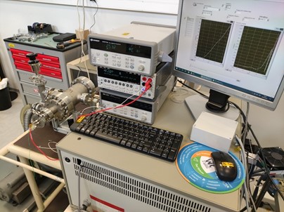
Figure 1. Setup overview
The vacuum in the chamber is achieved by using a vacuum pump connected through several valves that permit vent and pump into the DUTs chamber without the need to vent all the system each time the sample has to be removed, making this process more efficient agile. The vacuum section of the setup can be seen in figure 2.
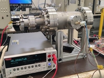
Figure 2. Detailed view onto vacuum section
Two kinds of electrical vacuum feed-throughs were necessary for this test. High-voltage feedthrough had to be used to bias and characterize the sensors, while specific high-temperature thermocouple feedthrough was used for temperature monitoring through a datalogger.
3. Results
The test setup was validated by testing empty sensor packages since more critical parameters: Temperature control and leakage current can be verified without the necessity of active samples. These trials revealed good electrical isolation of the whole system and demonstrated the capability of performing controlled heating up to 700°C with good results.
Preliminary testing of the sensors was performed up to 500° with dummy devices with reverse currents in the range of the uA for a total amount of 100 minutes. The reverse current of this dummy sensor at several voltages can be seen in figure 3, where no anomalies occurred, and smooth behavior was observed.
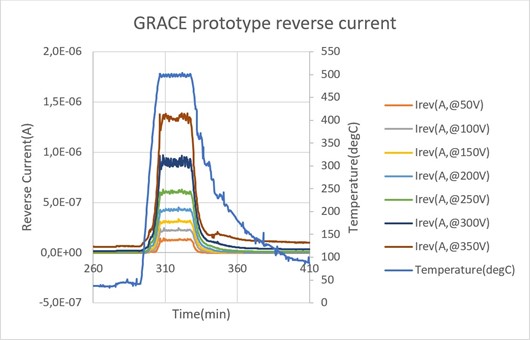
Figure 3. Dummy sensor monitored during 10 mins at 500degC
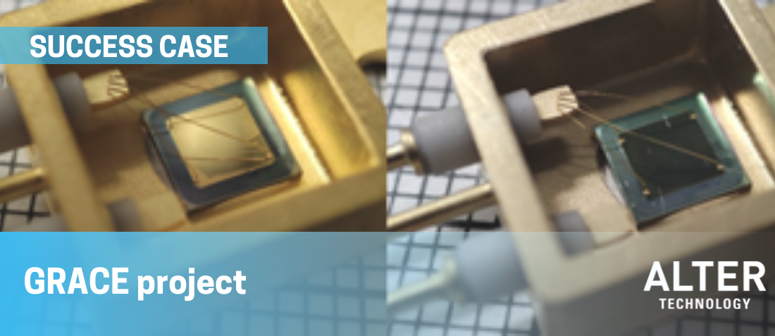
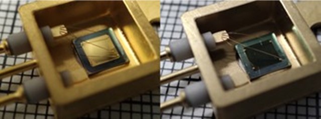
For the time being, a few dummy sensors have been tested, showing obvious changes in the external appearance of the surfaces (see the color change in figure 4) but keeping good electrical functionality. Additional mechanical tests performed in dummy dies after high-temperature exposure (die shear) revealed sufficient attach force of the die to the package.
Further testing in radiation conditions will be performed to validate the sensors in fully representative requirements inside a fusion reactor.
GET IN TOUCH TODAY!
Do you have questions? Contact us!
ALTER TECHNOLOGY LAB EXPERIENCE
- Lunar Regolith Test onto COTS Optoelectronics - January 18, 2023
- SiC reliability: Defects detection test for SiC devices - October 26, 2022
- Testing SiC Schottky Diodes for Heavy Ions Optimization - August 9, 2022

0 comments on GRACE PROJECT: Electrical Characterization at 500°C