Calibration Sources in Vacuum Conditions
- Posted by Alejandro López Moya
- On January 13, 2022
- 0
Thermal cycling test at extreme temperatures (between 93ºC and -178ºC) over some VIS-NIR calibration sources
Sometimes, customers request some particular test over their components, looking to know how they behave in extreme conditions (under vacuum, extreme temperatures, and even in different atmospheres when components are part of interplanetary missions).
Space is a harsh environment, and components and equipment must be ready to work reliably during life mission time.
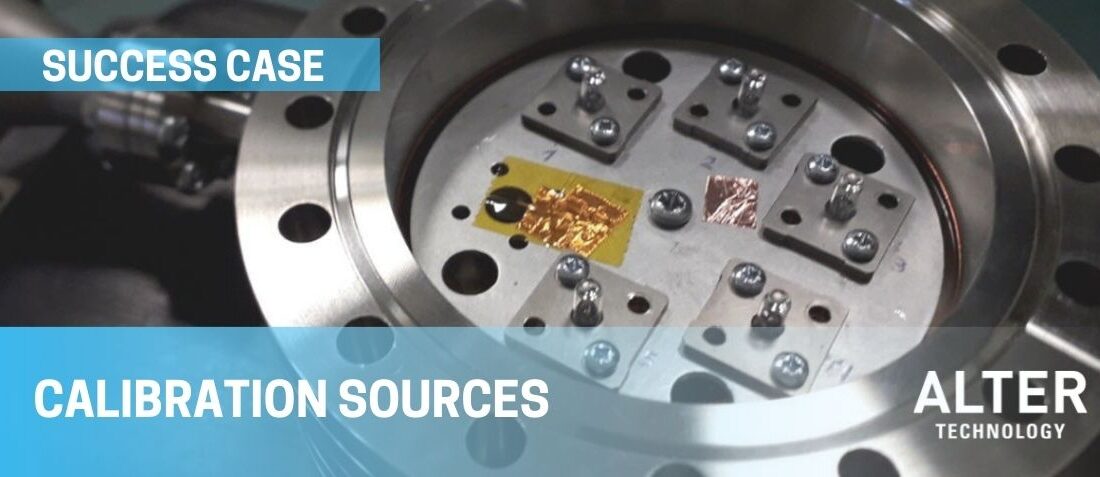
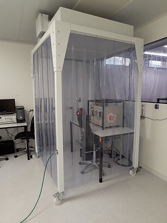
In this case, one of our best customers requested us to carry out a thermal cycling test at extreme temperatures (between 93ºC and -178ºC) over some VIS-NIR calibration sources (five samples at a time). At the same time, these sources were tested in vacuum conditions, and electro-optical characterization at different temperatures during cycling was requested. To go even further, the components needed to be tested in a clean environment, so all of them were tested in our ISO-5 Cleanroom (FED-STD-290E).
Test setup implementation was a big challenge for us.

Figure 1: Test setup inside clean room
About Thermal Cycling Test
The objective of thermal cycling testing is to determine the ability of parts and solder interconnects to resist extraordinarily high and low temperatures and their ability to endure cyclical exposures to extreme temperatures.
Most important points to take into account every time a light source is tested at extreme temperatures, while in vacuum conditions, are:
Perfect alignment of the light source with a light receptor. As the light source is inside the vacuum chamber and the receptor is outside, a perfect alignment system must measure optical power with maximum reliability. Small variations in alignment could cause significant differences in test results.
Thermal conductivity between samples and vacuum pot. A reliable thermal conductivity path must be ensured to allow samples to reach the required temperatures of the test. If not designed carefully, samples could never reach the temperatures requested.
Provide all electrical/optical paths properly to the inside of the vacuum pot. All electrical/optical paths components must be appropriately selected to work in the test conditions requested. All electrical and optical connections must be ready to support extreme temperatures and work reliably in vacuum conditions. If they are not prepared to work in these extreme conditions, they could distort measurements and result incorrectly.
All these points forced us to design and implement the test setup meticulously. Thanks to our mechanical design capabilities, which allowed us to design mechanical supports where VIS-NIR sources and optical fibers were placed, and thanks to all equipment and skilled personal available at ALTER, we finally designed a reliable test setup which allowed us to get a perfect characterization of the calibration sources at every temperature requested.
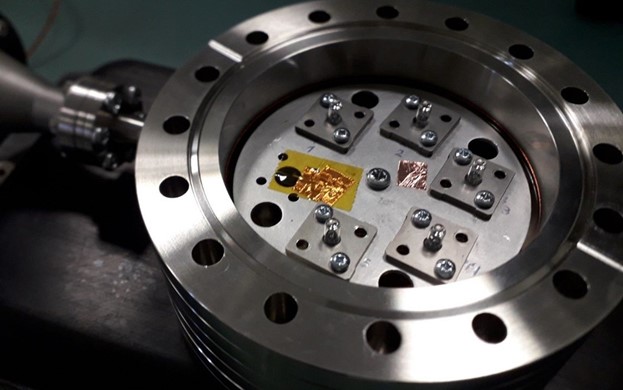
Samples were placed inside a vacuum pot, and this vacuum pot was put inside one climatic chamber fed with liquid Nitrogen. This system allows us to test components at temperatures from -196ºC to 250ºC. One of the multiple vacuum pumps available at our facilities was used. This pump will enable us to reach up to 1·10E-07 bar vacuum levels.

Figure 2: VIS-NIR calibration sources inside the vacuum pot
Every time a light source is measured in vacuum conditions, one of the most critical points to consider is getting a perfect alignment between the light source and receptor because one is inside the vacuum chamber, and the other one is outside. Small variations in alignment could cause big differences in test results, so it is a must to design the test set-up carefully.
Our mechanical design capabilities allowed us to design mechanical supports where VIS-NIR sources and optical fibers were placed. This allowed us to maintain a perfect alignment independently of the test temperature.

Another challenge when testing at extreme temperatures in vacuum conditions is getting a sound heat transmission. Thermal conductivity must be ensured to allow components to reach the required temperatures.
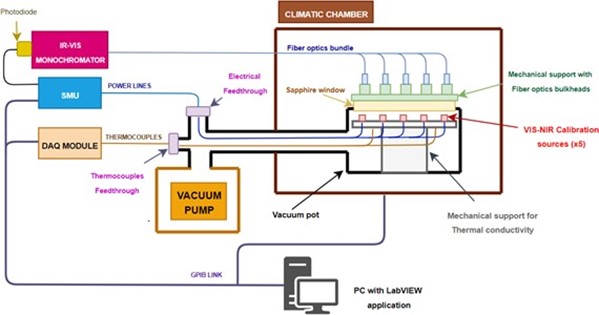
To allow Electro-optical characterization during thermal cycling, VIS-NIR calibration sources were powered at their nominal current by precision SMUs (Keithley 2602B). The customer required a wavelength sweep from 500nm to 2500nm, so one IR-VIS monochromator was used with one photodiode at its output. This PD was used to convert light emitted by calibration sources to the electrical domain. One Sapphire window was placed at the top of the vacuum pot to allow measure light at the outside, where an optical fiber bundle was in charge of driving light from every sample to the monochromator.
Temperature and vacuum were monitored along with the entire test, and finally, a LabVIEW application developed by ALTER team was responsible for monitoring and recording all data during the trial. The following block diagram shows the concept of test setup used:

Figure 3: Test setup block diagram
Although customer requirements for this test were quite demanding, finally, all calibration sources were correctly measured and continued with Qualification Test Sequence. Our customer ended pleased with our work.
ALTER TECHNOLOGY LAB EXPERIENCE
GET IN TOUCH TODAY!
Do you have questions? Contact us!
- IR SOURCES THERMAL VACUUM CYCLING CHARACTERIZATION - February 11, 2022
- Lasers Endurance Characterization in Vacuum Conditions – Test Setup - January 25, 2022
- Calibration Sources in Vacuum Conditions - January 13, 2022

0 comments on Calibration Sources in Vacuum Conditions