Ultrasonic Examination of Ceramic Capacitors by Scanning Acoustic Microscopy
- Posted by Francisco Javier Aparicio Rebollo
- On May 18, 2020
- 0
Ultrasonic examination and detection of hidden internal anomalies for the screening of defective parts and failure analyses.
Scanning Acoustic Microscopy (SAM) has proved to be the most effective tool for the non-destructive detection of very thin (even below 200 nm of thickness) internal anomalies (delamination, voids, cracks, and foreign material) within ceramic capacitors and other EEE parts. In fact, this technique is particularly useful to screen out internal defects without noticeable electrical signatures, neither initially nor after burn-in other stress tests, but that after prolonged operation turn into critical failures. This is the reason why this ultrasound inspection is systematically conducted for the early detection of potentially defective capacitors. Therefore, ultrasonic examination is routinely performed on ceramic capacitors in accordance with one of the following test methods.
Scanning Acoustic Microscopy is also a very effective method for the non-destructive inspection of ceramic capacitors showing anomalous electrical behaviour; in order to determine the failure mechanism and root cause of the detected misfunction. In the case of such a failure analysis scanning acoustic microscopy (also denominated scanning acoustic tomography, SAT) can be operated in different modes.
A detailed explanation of the working principle of the technique and the different scanning modes can be found elsewhere. The present post illustrates the capabilities of the ultrasonic inspection using as an example of the failure analyses of a ceramic capacitor that showed clear deviations in the electrical response.
C-SAM (Confocal Scanning Acoustic Microscopy)
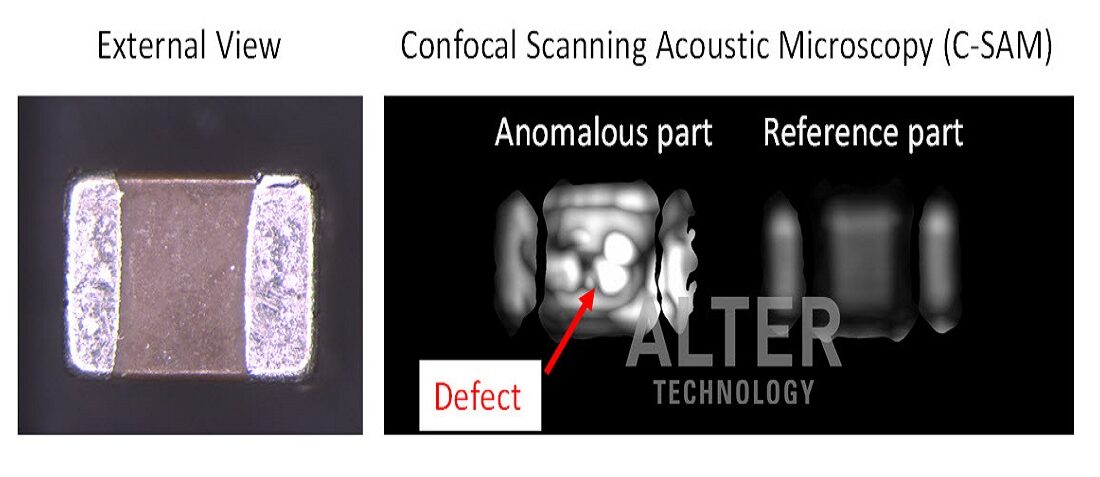
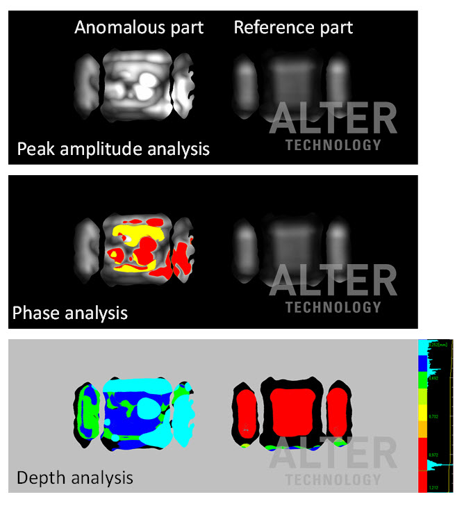
For the sake of comparison, scanning acoustic inspection was simultaneously conducted on the anomalous capacitor and a reference part. The next figure gathers the peak amplitude and phase analyses performed on the C-mode (confocal mode) of the microscope. A depth analysis was also performed to identify the location of the detected anomalies and other internal features.
The anomalous part has a defective layer at a depth of approximately 0.25 to 0.50 mm from the capacitor surface. This is clearly supported by:
- The stronger reflection from the anomalous part (top image in the figure above)
- Phase inversion sings, red/yellow areas, in the anomalous part (see image at the middle of the figure above)
- Depth analysis (bottom image in the figure above) indicates that the main reflection detected in the anomalous part is generated at a shallower level than that of the reference part, which comes from the bottom surface.
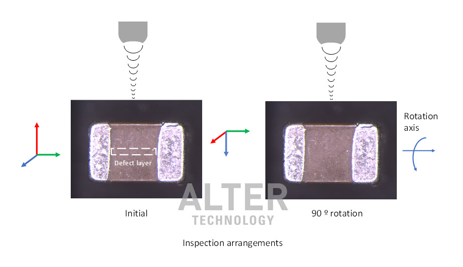
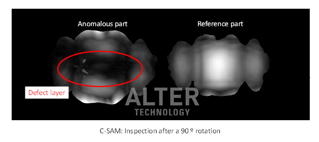
The next figure shows the C-mode scan registered after rotating both samples 90 º along the longitudinal axis. Thus, the defective layer is now was parallel to the acoustic beam. For this inspection, the beam was focalized on the bottom layer of the capacitor. The next figure compares the peak amplitude images of both samples. In this case, a dark shadow is detected rather in the middle of the anomalous part. The low intensity of the reflected beam by the defect in its way to/from the bottom surface of the capacitor.
B-SAM (virtual cross-section) and A-SAM verification
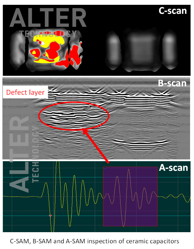
To confirm these findings, the image below also includes the B scan (virtual cross-section) and A-scan acquired at the defective area. B-scan clearly shows a defective layer within the top half the capacitor. In addition, the waveform of the echo reflected from this area (A-scan) confirms the phase inversion of the reflected beam. This is a behaviour that is typically ascribed to air interfaces (cracks, voids or delaminations) or the transition to a lower-density media.
Contact us
- Material Analysis Techniques for Electronic Components - May 6, 2022
- SAM: Survey to manufacturers and users - February 17, 2022
- What is a C-SAM Inspection? - January 29, 2022


0 comments on Ultrasonic Examination of Ceramic Capacitors by Scanning Acoustic Microscopy