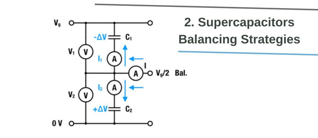
Supercapacitors Balancing Strategies
- Posted by doEEEt Media Group
- On February 9, 2023
- 0
The literature [3,4,6,7,8] categorizes balancing strategies by different properties like:
- energy dissipative behavior,
- balancing speed,
- the type of technology that is used or
- pricing
Thus, when it comes to choosing the right balancing strategy, it is important to know all the parameters and constraints of the specific application to make the right choice. In this note, we distinguish mainly between:
- active balancing and
- passive balancing
Active balancing involves the utilization of actively controlled switches or amplifying systems. [3, 8] Passive balancing utilizes shunts or self-regulating resistors to lower the effect of overvoltage. Compared to passive balancing, active balancing may be fast, in some cases energy efficient, but also relatively cost intensive. Passive balancing, on the contrary, is relatively slow, leading to a reduction of the charge-storing capabilities, but it is more cost-efficient than active balancing solutions.
Supercapacitors Passive Balancing with Resistors
Figure 2 presents an example of passive balancing with a resistor. The red and green arrows represent the corresponding physical current flow for the case where C1 has either over (+∆V) or under voltage (-∆V). The current for the balancing speed is adjusted (or restricted) by the resistance of the balancing resistors.
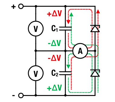
Figure 2: Circuit for supercapacitors passive balancing with resistor
The balancing resistors have to meet three main requirements:
- The resistance should be as low as possible to allow a fast balancing. This will be beneficial for a lifetime.
- The resistance should be as high as possible to minimize losses and self-discharge.
- The accuracy of the resistors/shunt should be sufficient (≤ 1%) to provide an accurate reference.
Clearly, it is necessary to find an optimum between short balancing times and low self-discharge. The balancing resistance would have to be the order of the equivalent series resistance RESR, to balance the supercars within the characteristic RC-time.
This is a theoretical consideration and not practical since it would mean we permanently short-circuit the SC. A good rule of thumb is one-tenth of the insulation resistance, i.e.
![passive balancing resistance by rule of thumb [12]](https://www.doeeet.com/content/wp-content/uploads/2023/02/passive-balancing-resistance-by-rule-of-thumb-12.png)
passive balancing resistance by rule of thumb [12]
With Vr as the rated voltage and Ileak as the leakage current (both values are given in the datasheet of the SC). Due to its magnitude, Rb balances differences in insulation resistances. The maximum current that can flow at ∆V is Imax = ∆V/Rb. The time to equalize an imbalance ∆V up to 95 % can be calculated with the:
![passive balancing time of unequal capacitors in series up to 95% [13]](https://www.doeeet.com/content/wp-content/uploads/2023/02/passive-balancing-time-of-unequal-capacitors-in-series-up-to-95-13.png)
passive balancing time of unequal capacitors in series up to 95% [13]
which can be well approximated with:

[14]
The resulting balancing times, given in Table 1, are indeed in the range of days. The daily self-discharge rate is about 41 % with the given balancing resistances. Thus, for many power applications, the resistance may even be reduced at the expense of charge-storing abilities and balancing speed.
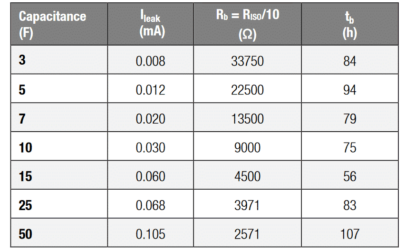
Table 1: Summary of supercapacitors balancing resistances and corresponding balancing times.
Supercapacitors Passive Balancing with Zener Diodes
An improved balancing time can be achieved if the resistor is replaced by a Zener Diode, as indicated in Figure 3. The arrows again indicate the electrical current flow in case of an imbalance. The Zener diodes constitute a variable resistor or a voltage-dependent switched resistor. Since the internal resistance is reduced at the breakdown voltage, it is possible to reduce the balancing time compared to the linear resistor drastically.
Diodes may also serve as general protection against reverse polarity. Especially for larger stacks, it can be advisable to place Zener diodes in parallel to metal oxide semiconductor field effect transistors (MOSFET). Compared to the accuracy of ohmic resistors, the breakdown voltage’s accuracy is usually relatively low. In total, the tolerances could be as high as around 10 %.

Figure 3: Circuit for balancing with Zener diodes.
A reduction of working voltage could still avoid possible overvoltages. For operations at higher temperatures, it might also be necessary to consider the shift of breakdown voltage due to the temperature coefficient.
The voltage dependence of the reverse current makes it difficult to calculate the balancing time accurately.[8] The current characteristics of commercial Zener diodes are often not given in the datasheet. It is,
![Zener diode passive balancing time of unequal capacitors in series [15]](https://www.doeeet.com/content/wp-content/uploads/2023/02/Zener-diode-passive-balancing-time-of-unequal-capacitors-in-series-15.png)
Zener diode passive balancing time of unequal capacitors in series [15]
Due to the strong voltage dependence of the reverse current, it may be necessary to adjust f from case to case to its effective value. Since the diode will, most of the time, operate well below its total power dissipation, we suggest f = 1/10.
Supercapacitors Passive Balancing with MOSFETs
Another type of balancing can be utilized with a MOSFET, as given in Figure 4. Like the Zener diode, the MOSFET constitutes a voltage-driven switch or variable resistor.
However possible to roughly estimate the balancing time based on the above expression for tb (see the previous section). A rough estimate can be made with the rated power dissipation of the Zener diode Pr, usually given in the datasheet. If the diode breakdown voltage is equal to the actual operating voltage, VR, we may substitute Rb* = Vr2 / Pr into the above expression for tb, and with f as the correction factor, we obtain:
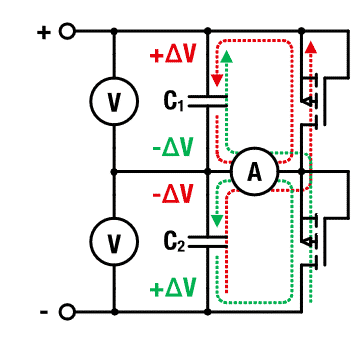
Figure 4: Supercapacitor balancing circuit with MOSFET
The arrows again indicate the electrical current flow, similar to the passive balancing in Figure 2. As soon as the voltage imbalance exceeds the threshold voltage of the MOSFET, the increased drain voltage leads effectively to a discharge of the overcharged capacitor. It is possible to think of the MOSFET as voltage-dependent resistors, which leads to improved balancing times compared to passive resistors.
Supercapacitors Active Balancing with Operational Amplifier
Any application that needs a shorter balancing time will have to apply an active balancing. Active balancing always involves integrated circuits such as an operational amplifier (OP-AMP), as illustrated in Figure 5. The circuit contains red and green arrows, representing the corresponding physical current flow for the case where C1 has either over (+∆V) or under voltage(-∆V).
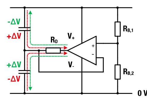
Figure 5: Circuit for supercapacitors active balancing with feedback amplifier
The balancing resistance, as used for the active balancing, is determined on the basis of the designated internal resistance of the OP-AMP, which is at least the order of 10 MΩ but usually even higher. To ensure the voltage detection at the inputs the balancing resistances RB,1 and RB,2 should be about 10 times smaller than the internal resistance of the OP-AMP. As a result, the loss through the balancing resistance can be as small as for the internal resistance of the SC.
However, a more significant cause of loss is the supply current, delivered through contacts V+ and V -. Depending on the type of OP-AMP the permanent supply current may be in the range from 1μA to 10mA. This may pose a technical obstacle, that needs to be considered at the conceptual design-in phase. The balancing current is provided by the output of the OP-AMP and regulated via the feedback loop. The damping resistance RD at the output of the OP-AMP is only as high as to prevent oscillation during the current regulation.
Supercapacitors Active Balancing with DC-DC converter
Another concept of active charge equalization consists of DC-DC converters, each connected across two neighboring cells, as illustrated in Figure 6. Due to the low losses of commercially available converters, this concept is more efficient in terms of balancing time and power burn than passive balancing.
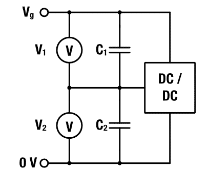
Schematic supercapacitors active balancing circuit with DC-DC Conversion.
Balanced buck-boost SC chargers are available on the market, which is suitable for various applications. Available for instance, are Analog Devices:
- LTC3351, Hot Swappable Backup Supercapacitor Charger
- LTC3128, Supercapacitor Charger, and Balancer
Additional information is also provided in the Würth Elektronik (WE) Webinar “WE Backup Your Application – A real life SC backup solution”.[11]
Although DC-DC converters constitute a relatively costly balancing strategy, they are, on the other side, also an elaborate and comprehensive solution. They may provide complete charging and hot-swappable charging solutions with low power consumption. The choice at the end is always with the developer.
- Miniature RF Connectors for high-performance testing - April 24, 2025
- Space-Grade components available for immediate delivery - April 10, 2025
- Managing EEE components for LEO and lower cost space missions - December 17, 2024

0 comments on Supercapacitors Balancing Strategies