What is a Resistor?
- Posted by doEEEt Media Group
- On October 14, 2022
- 0
This article explains the basic definition of electrical resistance, What a resistor is? as a passive electronic component, and its main application and technologies.
The very basic definitions:
What is Electrical Resistance?
Physical property in conductor or of a component which transforms electrical energy into heat
What is Electrical Resistor?
Resistors are passive electrical components that limits the flow of electric current.
Component R that has no significant distortion of phase at an applied voltage U and the resulting flow of current I
Resistors, like inductors and capacitors, are passive electronic components that are quite simple in theory but rather more complex when the behaviors of real-world devices are considered. Any resistor that one can build or buy is non-ideal in some respect, rendering it unsuitable for some purposes; the various products available offer different balances of imperfection to be found good enough for others.
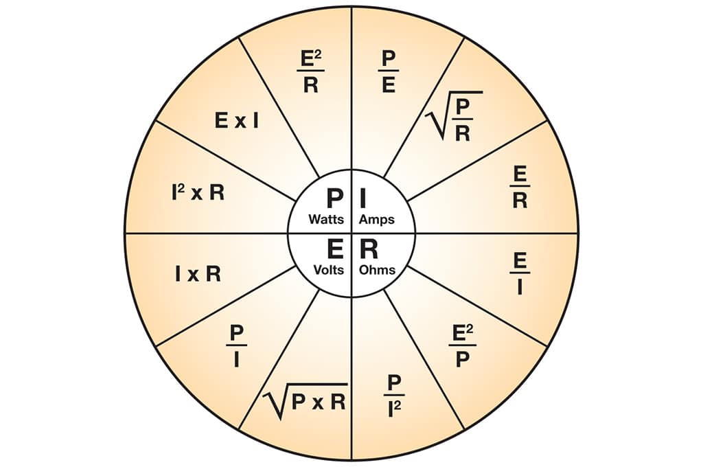
Resistors can be found in almost all electrical networks and electronic circuits. The resistance is measured in ohms. An ohm is a resistance that occurs when a current of one ampere passes through a resistor with a one-volt drop across its terminals. The current is proportional to the voltage across the terminal ends. This ratio is represented by Ohm’s law basic equation [1] and related equations for power, current, voltage, and resistance in Figure 1.:
![Ohm’s law equation [1]](https://www.doeeet.com/content/wp-content/uploads/2022/10/Ohms-law-equation.png)
Ohm’s law equation [1]
where:
U= applied voltage;
R= resistive value;
I= resulting current

Figure 1. Ohm’s law power, current, voltage and resistance equations
Despite Ohms’ law being one of the most frequent used relationships for components and circuits, there is some limitation to it validity:
- high frequencies (relaxation, skin effect)
- high field strengths (flashovers at highly resistive materials)
- very low temperatures (superconductivity)
Resistors have several properties besides their rated resistance, such as their temperature coefficient, resistor noise, and power rating. These resistor properties can be important to take into account depending on the application.
Resistors are used for many purposes. A few examples:
- delimit electric current
- voltage division
- heat generation
- matching and loading circuit
- control gain
- fix time constants
- current measurements
They are commercially available with more than nine orders of magnitude resistance values. They can be used as electric brakes to dissipate kinetic energy from trains or be smaller than a square millimeter for electronics.
Resistor technologies differ in features and range of electrical parameters covered. Let’s start our course by learning some basics about them and what technologies are available today.
Resistor Terms and Definitions
Nominal Resistance
The designed resistance value is usually indicated on the resistor.
Power Rating
Maximum allowable power at rated temperature. Some of our chip resistor arrays and networks specify the whole power rating as a package.
Rated Temperature
The maximum ambient temperature at which the power rating may be applied continuously. The rated ambient temperature refers to the temperature around the resistor mounted inside the equipment, not the air temperature outside the equipment.
Rated Terminal Part Temperature
The maximum terminal part temperature of the surface mount resistor at which the power rating may be applied continuously. Includes the temperature rise by self heat generation.
Derating Curve
The curve that expresses the relation between ambient temperature and the maximum allowable power, which is generally expressed in percentage.
Rated Voltage
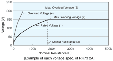
Maximum allowable D.C. or A.C. voltage (RMS) can be continuously applied to a resistor or a resistor element under the rated ambient temperature or terminal part temperature, which is calculated from the rated power and nominal resistance using the following formula.

The rated voltage shall not exceed the max. Working voltage.
Critical Resistance
The maximum nominal resistance value at which the rated power can be applied without exceeding the maximum working voltage. The rated voltage is equal to the max. Working voltage at the critical resistance value.
Max. Working Voltage
Maximum D.C. or A.C. voltage (RMS) that can be continuously applied to the terminations of a resistor. However, the maximum value of the applicable voltage is the rated voltage at the critical resistance value or lower.
Maximum working and rated voltage are calculated by direct-current voltages based on rated power. The sine wave is assumed for the alternate current so the peak voltage should be √2 times the maximum working voltage. When the waveform is not a sine wave or the resistance value exceeds the critical resistance, please contact the manufacturer/consult the product datasheet for the applicable peak voltage.
Overload Voltage
The allowable voltage is applied in 5 sec. Under short time overload test. Overload voltage shall be 2.5 times of rated voltage or max. Overload voltage, whichever is lower.
Max. Overload Voltage

Figure 2. The maximum value of resistor overload voltage – for example: source KOA
Dielectric Withstanding Voltage
In the voltage proof test, A.C. voltage (RMS) that can be applied to a designated spot between the electrode and the outer coating in one minute (JIS C5201-1 4.7).
Temperature Coefficient of Resistance(T.C.R.)
Relative variation of resistance between two given temperatures when the temperature is changed by 1K.
Source: Passive Components Blog
- Space-Grade components available for immediate delivery - April 10, 2025
- Exclusive stock on doEEEt: How to access and request - April 10, 2025
- Managing EEE components for LEO and lower cost space missions - December 17, 2024


0 comments on What is a Resistor?