One Turn Inductors Explained
- Posted by Kemet Electronic Corporation
- On March 24, 2022
- 0
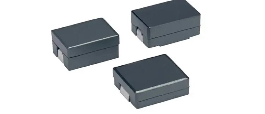
Flat wire, “one turn” inductor construction design, enables high efficiency at large currents ideal for high switching frequency applications. Kemet blog explained its basic construction and features.
Inductor Basics
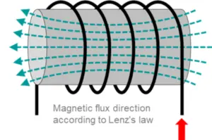
Engineers know this like they know that capacitors are parallel plates, that inductors are coils of wire. That notion is beat into our heads from the early days of circuits 1. The world was so simple back then, current flowed in one direction, wires were perfect conductors, and capacitors held charge forever. Inductors store energy via a built-up magnetic field. As current flows through the coil of wire a magnetic field is created and sustained by the core material around which that coil is wrapped. When that magnetic field collapses it produces a current in the coil of wire. Fundamentally, an inductor is the dual of a capacitor. Where a capacitor is resistant to changes in voltage, an inductor is resistant to changes in current.

The One Turn Inductor
Inductors don’t always have to be tightly packed coils of wire. Yes, the number of turns is one factor that gives rise to the overall inductance. According to the equation below, it is a squared factor and, therefore, a major one.
But it isn’t the only factor. The relative permeability of the core, which is determined by the material composition of the core itself, is another factor. It is possible to recover some of the inductance lost by reducing the number of turns by improving the permeability of the core by selecting inductors with high permeability ferrite core material.
It’s All About DCR and Loss
What’s so great about a one-turn inductor? OK, so no matter how great your core material is, you won’t recover all the inductance by going to one turn. But you don’t always need a ton of inductance. As switching frequencies increase, it would be best if you had less and less inductance. Still, turns come at a cost. One of the biggest components of loss in an inductor is the DC copper loss. If you look at the equation of resistance of a wire:

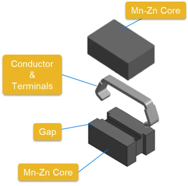
One turn inductor construction; credit Kemet Electronics
The total resistance is equal to the resistivity, ρ, which is a material parameter multiplied by the length of wire, L, divided by the cross-sectional area, A. That means that if you wanna reduce the loss of your conductor you can make it shorter or fatter (or of a different material). We’re all kinda stuck with copper for many reasons, so the resistivity is what it is. And if you make the wire fatter you increase the overall size of your component, which no one wants. So, you’re left with making it shorter.
The reduction of DCR is necessary to reduce loss. But what’s so bad about loss? Well, that power loss must go somewhere and in electronics it generally becomes heat. Unchecked heat is bad for other components and can be unsafe.
One last benefit of these assembled inductors is that the inductance can be tightly controlled by adjusting the gap size between the two clamshells. That results in inductors that can be finely tuned to ensure maximum power delivery at their operating frequency.
Focus Applications of One Turn Inductors
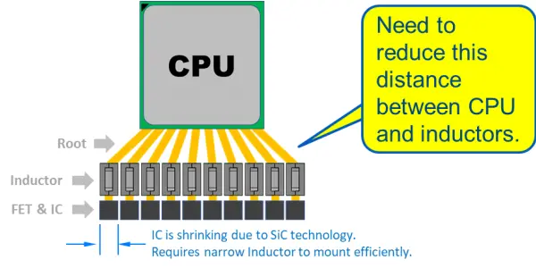
The inexorable march of electronics is generally one that goes to a higher power while shrinking in size. That is the reason why one turn large current power inductor has been developed. The one-turn design enables high current operation while reducing losses and size. More inductors and more voltage rails can be packed in a tighter space.

One turn inductors narrow chip design benefits application example; credit Kemet Electronics
Source: Kemet Electronics
- Decoding The DC-Link - June 8, 2022
- High Reliability: Tantalum Capacitors on the Front Lines of Defense - June 3, 2022
- One Turn Inductors Explained - March 24, 2022


0 comments on One Turn Inductors Explained