Low Inductance, Direct Power DC Bus for Electric Drive Systems
- Posted by doEEEt Media Group
- On May 4, 2021
- 0
Recently, a team at Sandia National Laboratories developed and patented an interesting approach to DC power bus for electrical vehicles with low resistance, low inductance but also sufficient capacitance to smooth out voltage ripple.
As DC currents increase along with switching frequencies in applications such as electric vehicles and hybrid electric vehicles, the performance demands on the DC power bus go beyond just the IR drop (i.e. voltage drop) and thermal considerations. That bus must now have very low inductance at higher frequencies into the hundreds of kilohertz, driven by design demands and the increased use of wide bandgap devices (WBG) represented by silicon carbide (SiC) and gallium nitride (GaN) switches.
The bus must have low resistance and low inductance but also sufficient capacitance to smooth out voltage ripple. Unfortunately, the same capacitors used for that second attribute are detrimental to the first one due to their interconnect and internal parasitics. Different approaches can be used to try to the multiple conflicting goals, in addition to simply adding more bulk capacitance.
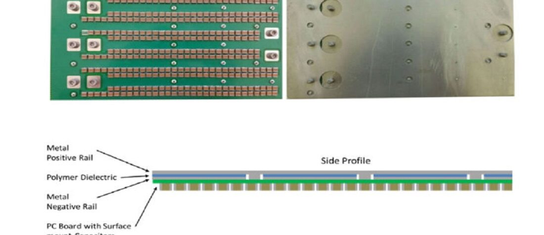
Sandia National Laboratories design uses a layered, PC board-like construction with two metal planes separated by a polymer dielectric to provide “planar” capacitance, Figure 1.
This base capacitance is boosted by a large number (in the hundreds) of small multilayered ceramic capacitors (MLCCs) — rather than the customary electrolytic or film capacitors — connected between the planes using standard PC board vias, Figure 2.
This approach provides both electrical and thermal benefits. The spread-out placement of so many capacitors reduces shunt impedance to high-frequency current components, and the flat ceramic capacitors can tolerate higher temperatures and support better airflow. There are other benefits as well. In existing applications, the positive and negative (often called ground) rails use bus bars, and these are separated by a large area; as the magnetic field lines cross this larger area, there is a higher effective inductance due to the large current loop. The Sandia Laboratories plate-based approach greatly reduces the inductance by decreasing the area of the current loop.
Their prototype board used 2-ounce cladded PC-board material and measured about 6 × 11 × 0.062 inches thick (150 × 280 × 1.6 mm). It was populated with 336 0.15 µF/1000 V MLCC devices (with X7R dielectric and AEC – Q200 qualified, for automotive use). Total capacitive was 50.4 µF, which their models and simulations indicated would be sufficient to keep ripple below a target value at 100 kHz.
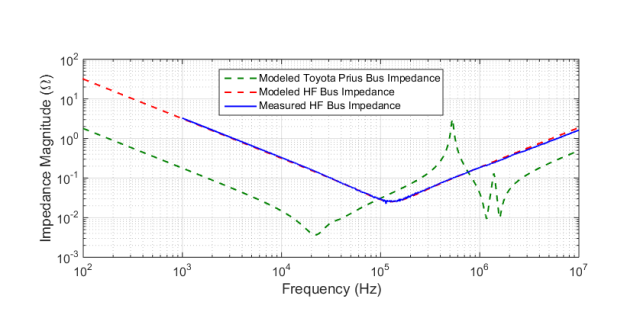
In addition to extensive modelling, they tested this design from 100 Hz to 10 MHz with an impedance-measurement instrument, Figure 3, and those results closely matched their model.
They also compared their results to an available model of a bus used in a similar way in a Toyota Prius. Their bus had somewhat superior performance, was physically smaller, and could withstand higher temperatures.
Source: Sandia National Laboratories
- Space-Grade components available for immediate delivery - April 10, 2025
- Exclusive stock on doEEEt: How to access and request - April 10, 2025
- Managing EEE components for LEO and lower cost space missions - December 17, 2024


0 comments on Low Inductance, Direct Power DC Bus for Electric Drive Systems