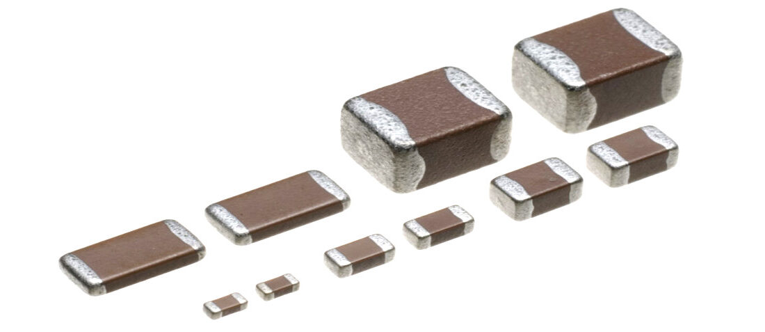
Five not-so-general-purpose MLCC
- Posted by doEEEt Media Group
- On June 3, 2019
- 0
The MLCC capacitor is one of the most widely used passive components today. Approximately 1000 billion multilayer ceramic capacitors are produced per year. Manufacturers have improved the electrical performance of these passive components through incremental progress in design, manufacturing methods, and materials. Today’s chip MLCC capacitors are smaller and offer better reliability and improved electrical specifications as compared to their predecessors. They offer impressively high capacitance values, high-temperature values (over 200oC), and ultra-low loss. Furthermore, today’s surface mount MLCC capacitors have a higher capability to withstand thermal expansion and bending.
These characteristics make them a popular choice today for many applications ranging from commercial and consumer electronics up to high-reliability aerospace, medical and downhole circuits.
In this article, we take a look at 5 multilayer ceramic capacitor types, each designed for a unique application.
High Q chip MLCC capacitors for RF/Microwave applications
Surface mount MLCC and porcelain capacitors are widely used in high-frequency applications. These passive elements are common in electronic circuits for RF power generators, RF power amplifiers, cellular communication systems, satellite communication systems, wireless communication devices, and magnetic resonance imaging systems.
High Q ceramic and porcelain capacitors for RF/microwave applications are enhanced to deliver optimal performance at high frequencies. C0G, a Class I dielectric material, is widely used in the construction of high Q MLCC capacitors for high-frequency applications.
In RF/ microwave systems, high Q ceramic and porcelain capacitors are used for a wide spectrum of applications including DC blocking, RF coupling, and impedance matching applications. Today’s high-frequency systems are highly advanced and demand capacitive elements that meet specific performance requirements. Some of the key frequency dependent parameters that a designer should consider when selecting a capacitor for these applications include quality factor (Q), equivalent series resistance (ESR), and impedance. For some applications such as coupling and DC blocking, it is also important to consider the insertion loss of a component.
The equivalent series resistance of a capacitor determines power dissipation in a component, and minimizing it helps to reduce power loss. The value of this parameter depends on dielectric losses and ohmic resistance losses in metallic electrodes and terminations. At RF frequencies, metal losses in electrodes and terminations are the main contributor to ESR. In comparison, at low frequencies, dielectric loss is the main contributor to equivalent series resistance. The significant increase in metal losses at high frequencies is mainly due to skin effect. A low ESR value yields a high-quality factor.
The frequency of operation of RF/microwave systems varies depending on the application. To meet the requirements of different systems, high Q MLCC capacitors are available for a wide frequency range. In addition, these capacitive elements come in a broad range of capacitance values. Apart from high-quality factor, most RF/microwave applications also require components with ultra-low dissipation factor and equivalent series resistance.
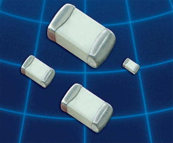
Fig.1. High Q MLCC; image credit: Johanson Technology
Non-magnetic chip MLCC capacitors for medical applications
The performance characteristics of capacitors are mainly determined by the materials used to construct them. One of the key characteristics to consider when selecting capacitors for medical applications is the magnetic properties of the materials used. MLCC capacitors with materials that exhibit magnetic properties are not suitable for medical applications such as magnetic resonance imaging (MRI) scanners, hi-rel medical systems, test and diagnostic equipment, and laboratory analysis systems, because their parasitic magnetics reduces the quality of signals and images. Such applications require non-magnetic MLCC capacitors.
Some of the materials that are commonly used for constructing terminations for MLCCs include nickel, copper, and Silver/palladium (Ag/Pd). Copper terminations are commonly used for base metal electrode capacitors while silver is widely used for precious metal electrode capacitors.
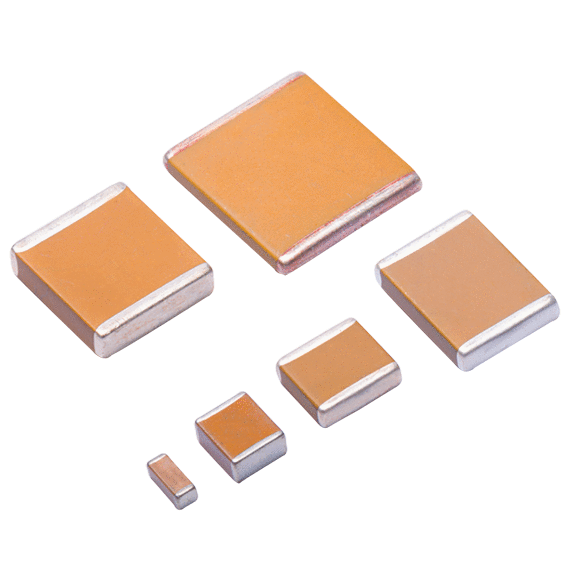
Fig.2. Non-magnetic medical grade MLCC; image credit: Exxelia
Nickel exhibits magnetic properties, and nickel terminations are not suitable for use in medical applications. Ag/Pd terminations do not exhibit magnetic properties, and they can be used for non-magnetic applications. Nevertheless, Ag/Pd terminations are hardly used in today’s non-magnetic capacitors because they have inferior solder leach resistance and require low melting point solders (typically lead-based solders).
The regulations by Restriction of Hazardous Substances (RoHS) discourage the use of lead-based solders. This has resulted in increased usage of lead-free solders in PCB assembly. Compared to lead-based solders, RoHS compliant solders have high-temperature requirements. Use of high temperatures on Ag/Pb terminations causes solder leaching problems. Although these terminations are non-magnetic, this problem makes them an unsuitable option for medical applications.
Unlike Ag/Pb terminations, copper terminations do not exhibit solder leaching problems, and they are commonly used in capacitors for non-magnetic applications. These terminations are usually plated with silver or tin. Some of the dielectric materials that are commonly used for constructing capacitors for non-magnetic applications include C0G/NP0, X7R, and high-Q dielectrics.
Apart from medical applications, non-magnetic MLCC capacitors are also used in other sectors including military, telecommunication, and aerospace industries. These passive components are common in audio amplifiers and hi-rel aviation systems.
Multilayer ceramic capacitors with flexible terminations
Some electronic components are highly susceptible to cracking, especially when they are exposed to extreme stress. When a printed circuit board is subjected to shock or vibrations, the stress is transmitted to components. This stress can cause some components to crack. Cracking is a major cause of failure in surface mount multilayer ceramic capacitors.
Exposing a conventional multilayer ceramic capacitor to harsh environmental conditions can lead to cracking and failure of the component. Since the demand for capacitors that can withstand harsh environments has been growing, manufacturers have made significant advancements in designing capacitors that have a high tolerance to cracking. Advancements in materials technology have helped manufacturers to produce termination designs that are well suited for harsh conditions.
Stress concentration in standard terminations is a major cause of cracking. Capacitors that are used in harsh environments are more susceptible to this type of component failure. Using flexible terminations helps to alleviate stress concentrations and prevent cracking. As compared to capacitors with rigid terminations, components with terminations that can expand or compress have higher reliability and longer lifetime.
A capacitor can be exposed to stress when an electronic system is being used or during printed circuit board (PCB) assembly. The tolerance of a capacitor to stress mainly depends on the flexure that its terminations are designed to provide as well as the conditions that it is exposed to. Since most component failures are due to mechanical damage caused by board flexure, the use of flexible terminations helps to significantly improve the reliability of chip MCLC capacitors.
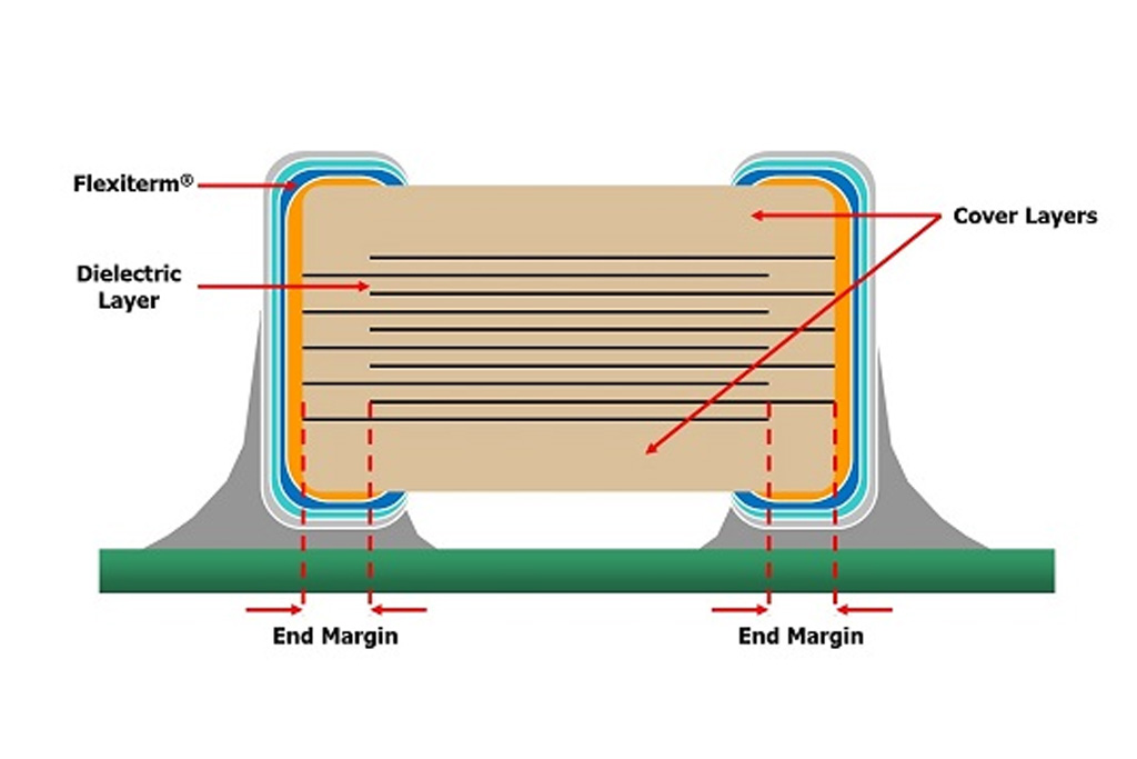
Fig.3. Flexible termination “Flexiterm” MLCC structure, image credit: AVX
Some applications expose capacitors to harsh conditions such as extreme pressure, high temperatures, and extreme shock and vibrations. Such applications subject electronic circuit boards to stresses and demand components that are optimized to withstand exposure to harsh environmental conditions. Some of the industries that require such components include automotive, oil and gas, and aerospace industries. Multilayer ceramic capacitors with flexible terminations are widely used in such industries.
Reverse geometry chip MLCC capacitors
An ideal capacitor can transfer its stored energy to a load instantaneously. Unlike ideal capacitors, an actual capacitor has parasitic elements that prevent the instantaneous transfer of stored energy to a load. Due to these parasitic elements, an actual capacitor is usually modeled as an RLC circuit. The RLC values represent equivalent series resistance (ESR), equivalent series inductance (ESL), and equivalent series capacitance (ESC). Whereas the ESR determines power loss in a capacitor, the ESL of a component determines the speed at which energy is transferred to a load.
The equivalent series inductance of a capacitor is greatly dependent on the size of its current loop. Capacitors with small current loops have low ESL and vice versa. Today’s high-performance electronic systems demand capacitive elements with low parasitic inductance. One of the most effective ways of reducing the equivalent series inductance of a capacitor is by rotating the orientation of a component by 90o. Reducing the inductance of a capacitor helps to increase the speed of transferring energy to a load.
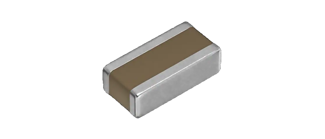
Fig.4. Reverse geometry MLCC, image credit: TDK
Reversing the geometry of a chip MLCC capacitor shortens the current path through a component. This is achieved by attaching the terminations along the length of a component. For a standard chip MLCC, the terminations are attached along the width of a component, and the current loop is longer. Surface mount MLCC capacitors with reverse geometry have lower inductance as compared to standard components, and they are an ideal choice for decoupling applications in high-speed electronic systems. The parasitic inductance of these components is approximately 60% lower than that of standard MLCCs.
As compared to standard multilayer ceramic capacitors, capacitive elements with reverse geometry have lower equivalent series resistance and higher resonant point. Since MLCCs with reverse geometry have lower inductance than standard components, using them in electronic circuits helps to reduce the number of components and save valuable printed circuit board space. Reducing the number of components significantly helps to improve the overall reliability of a circuit.
Apart from low parasitic inductance, chip MLCC capacitors with reverse geometry also provides high-frequency noise suppression and stabilization of power line voltage. These capacitors are used in a broad spectrum of applications including network systems, high-speed power supply decoupling, CPU power line decoupling, and GPU power line decoupling. These capacitors are common in electronic circuits for smartphones, PCs, camcorders, automobiles, and so on.
“Tip & Ring” chip MLCC capacitors
Chip MLC capacitors have a broad spectrum of applications in the telecommunication industry. In ringer circuits, MLCCs are used to block DC voltage (typically -48 volts) and allow AC signal (16-25Hz AC, 70 to 90Vrms) to pass. Multilayer ceramic capacitors for use in this application are referred to as “Tip & Ring” capacitors.
Traditionally, electronic designers use high voltage film capacitors in telecommunication ringer circuits to block DC telephone line voltage. Leaded film capacitors for telecommunication ringer circuits are large in size and occupy considerable space on a printed circuit board. In comparison, a “Tip & Ring” chip MLCC capacitor is smaller and occupies less space on a PCB. It is also lighter.
X7R, a Class II dielectric material, is widely used in the construction of “Tip & Ring” multilayer ceramic capacitors. As compared to film capacitors, these capacitors have lower equivalent series resistance (ESR), and better temperature performance. Moreover, “Tip & Ring” MLCC capacitors offer excellent high-frequency filtering.
“Tip & Ring” MLCCs are suitable for a wide range of applications in the telecommunication industry. Apart from telecommunication ringing circuits, they are also used in satellite dishes, wireless base stations, analog and digital modems, ATM hardware, Facsimile machines, and SMPS snubber circuits.
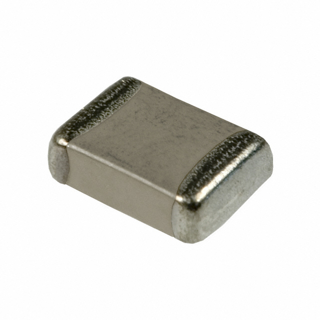
Fig.5. “Tip & Ring” MLCC chip; image credit: Murata
Source: Capacitor Faks blog
Featured image credit: TDK EPCOS
- Managing EEE components for LEO and lower cost space missions - December 17, 2024
- Filtering Characteristics of Parallel-Connected Fixed Capacitors in LCC-HVDC - November 21, 2024
- ALTER SPACE TEST CENTER: testing approaches for New Space - September 30, 2024


0 comments on Five not-so-general-purpose MLCC