Designing Custom Inductors: Tips and Tricks
- Posted by doEEEt Media Group
- On June 6, 2019
- 0
Choosing the Inductor Value
Many engineers believe that there is a single inductor value that should be used for a given design. They may have read an application note, or a textbook, that sets the value of the current ripple in a buck converter, for example. I would caution becoming complacent in this technique. In reality, the range of inductors that can work in a converter is actually very large [2]. It can be as much as 40 to 1, corresponding to a ripple current to dc current ratio ranging from 5% to 200%. The 200% value may seem overly large, meaning that the buck converter is running in discontinuous mode. However, there are some soft-switching advantages that can be gained in this mode.
Some of the most sophisticated and dense converters are designed that way. This is sometimes hard for inexperienced engineers to accept, but there is no “right” answer for the inductor value. Experimentation and testing is the best way to realize the optimal design for your application. Don’t be afraid of design iteration – just learn how to be efficient with your time. Figure 1 shows the application for which we want to design an inductor—a 300 W buck converter running at 300 kHz.
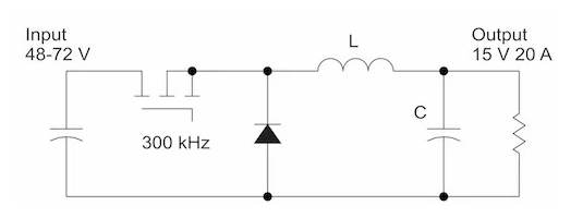
Figure 1. Buck power converter switching at 300 kHz.
The inductor value determines the amount of ripple current in the converter. Figure 2 shows simulations with two different values of ripple, one at 20% of the load current, and one at 80% of the load current. With modern switching devices, and good quality output capacitors, either of the designs can work well. The small inductor with 80% ripple will have better efficiency in magnetics, but the peak currents will be higher and the output voltage ripple will be greater. The true numbers for overall performance can be rapidly simulated as in [3], and verified by measuring the actual hardware for each case. When we design a converter, we make it easy to swap out magnetics parts so a variety of different designs can be quickly evaluated.
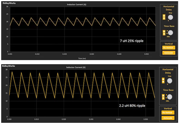
Figure 2. Ripple currents for different inductor values.
Choosing the right inductor value is an iterative process. The full implications of the choice do not become apparent until each value is realized in the core and winding design process, so it is important not to fix the value of the inductor until the magnetics iterations have been assessed.
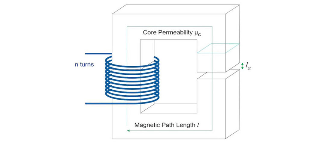
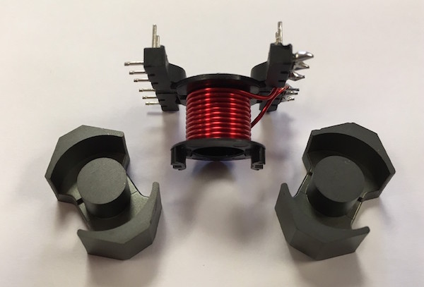
The basic parts of the inductor to be designed are shown in Figure 3. We need to choose a core area, the number of turns, core material, and gap to design an inductor. The first step that we take is selecting the area of the core.
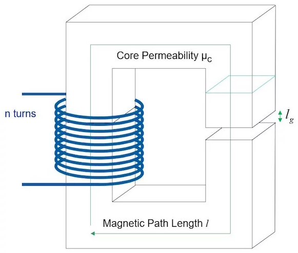
Figure 3. The basic parts of a custom-designed inductor.
There is a very wide range of core areas that can be made to work for each design. We encourage beginning designers to experiment with different values to rapidly gain experience and to build a knowledge base. Figure 5 shows the range of choices. The lower end is bound by the size of the gap that will result (you don’t want it to be too big) and the thermal performance of the inductor. If you have good cooling, and space in the design is very tight, you will choose a value of core area at the bottom end of the range.
The largest area is about 25 times bigger than the smallest. Above this size, the gap in the core becomes too small to be controllable, and the core area is wasted. As the larger size is approached, the temperature of the part will reduce. Most magnetics manuals, textbooks, and handbooks try to reduce the range of usable core area to a single value for the given energy storage. This is an artificially constrained situation since there is no input for cooling in these design guides. It is better to try the range available and to do at least a paper design for several different cases to see the implication of the choices.
For our buck example, we first calculate the inductance multiplied by the peak current squared. Taking a 7 μH value, the peak current seen in Figure 3 is 25 A. The product is then plotted on the x-axis of Figure 4, and the minimum core area to use is about 0.45 cm2. The subsequent core chosen is an RM8 core from Ferroxcube or TDK, shown in Figure 1. This core is readily available and is a popular choice in the power supply industry.
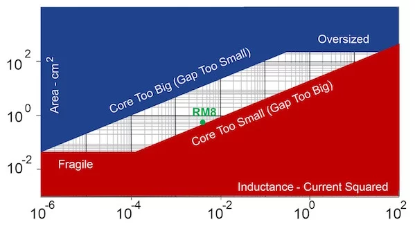
Figure 4. Starting the design process by choosing a core. A wide range of core sizes can be used.

Figure 5: Starting with the one equation.
Once the core has been selected, we apply the single design equation that has been discussed in previous articles on inductor design [4]. We already know every quantity in the equation of Figure 6 except the number of turns. It is good to reiterate here that the designer must be careful to enter the correct value of the saturation flux for the core, Bs. Recently, some core manufacturers have given artificially inflated values for this quantity [5] in material data sheets. If you see a number much higher than 0.3 T for a ferrite, proceed with caution.
For this design example, the minimum number of turns is 11. Now we can have some fun with the design. Knowing that we don’t need to worry about anything but the number of turns, we can try many different ways to place the windings in the core bobbin. The choices will have profound effects on the performance of the part.
The simplest and cheapest way to wind an inductor is with a single layer of wire from one end of the bobbin to the other. This will result in a low self-capacitance and resulting in high resonant frequency. However, as you can see in Figure 6, the dissipation is unacceptably high. There is not enough copper area, to carry the DC current.
Figure 6. Initial single layer winding
Next, we try using multiple layers of winding. It is here that we face almost endless choices, even for a simple single-winding inductor. If we wind two layers with a single strand of wire, the dissipation is cut to 2.3 W. There are several different ways to wind two layers, and careful attention should be paid to the construction as this tends to be the highest capacitance configuration. The two-layer winding case is covered in detail in [6]. The simplest construction technique is to wind the layers out and back continuously, and this results in poor design in many cases.
Two layers can also be wound with two separate strands of wire. Less copper is used, and since the current waveform is mostly DC with the 7 μH inductors, the higher dc resistance gives more loss at 3.6 W. If three layers of two-strands are used, the losses reduce back to 2.4 W, and capacitance will be reduced from the simple out-and-back two-layer winding.
At high frequencies, designers may try winding with foil to provide better window fill factor and hopefully reduce the high-frequency losses. If the conventional foil is used, as shown in the left diagram of Figure 8, the winding loss is no better than the wire wound inductor. Using a helical flat winding structure, as shown with the copper rotated 90 degrees, provides a considerable drop in dissipation to 1.3 W.
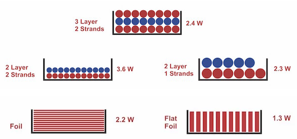
Figure 7. Foil winding (top) and flat foil winding (bottom).
Once several winding options have been explored and either tested or analyzed, you can explore reducing the inductor value. For example, with a 2.2 μH inductor, only 5 turns are needed to support the new peak current of 32 A. A flat foil design can then be reduced to just 0.5 W of dissipation, and the foil winding reduced to 1.2 W. Due to proximity effect losses, there is really no benefit in using a smaller inductor value if a conventional foil construction is being used. In fact, a single layer winding performs better than the foil. A further reduction could probably be achieved using litz wire in place of solid round wire.
References
- Hands-on workshops for power supply design www.ridleyengineering. com/workshops.html
- Choosing the Inductor for a Buck Converter, Ridley Engineering Power Supply Design Center.
- Design and simulation using RidleyWorks® • Inductor design articles 101-103, Ridley Engineering Design Center.
- Misleading Bmax specification from vendors, Article 102.
- Different winding techniques for Flyback Winding with two layers.
Source: EE Power article
by Dr. Ray Ridley at Ridley Engineering. Inductor manufacturers have made great progress in the families of standard parts. The selection of off-the-shelf parts in this category have increased dramatically in the past 10 years. However, more and more engineers are designing their own inductors and transformers from scratch.
- Space-Grade components available for immediate delivery - April 10, 2025
- Managing EEE components for LEO and lower cost space missions - December 17, 2024
- Filtering Characteristics of Parallel-Connected Fixed Capacitors in LCC-HVDC - November 21, 2024


0 comments on Designing Custom Inductors: Tips and Tricks