Conventional vs. Planar Switching Power Transformers
- Posted by doEEEt Media Group
- On July 11, 2020
- 2
Escalation in the use of higher frequencies for today’s power-conversion applications has designers increasingly looking at planar magnetics devices over traditional transformers.
The demand for higher efficiency and smaller packages has been the driving force behind advances in switch-mode power-conversion topologies including buck, boost, flyback, forward converters, and others. Requirements for smaller devices coupled with the demand for higher power densities are being achieved via innovative component packages.
Traditional MOSFET power-conversion topologies have responded to these demands through the development of devices designed to operate with lower switching losses at higher frequencies. Over the past several years, the emergence of wide-bandgap (WBG) devices capable of operating at yet even higher frequencies has accelerated the drive toward higher efficiency and smaller packaging. Planar magnetics devices are replacing traditional transformers and inductors in some of these higher-frequency power-conversion applications.
This article offers a brief answer to two questions in this arena: What’s the difference between conventional and planar magnetics? How do you choose the right one for your application?
Conventional vs. Planar Transformer

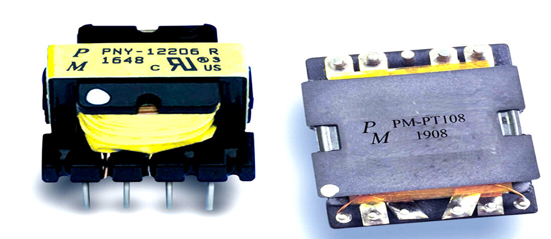
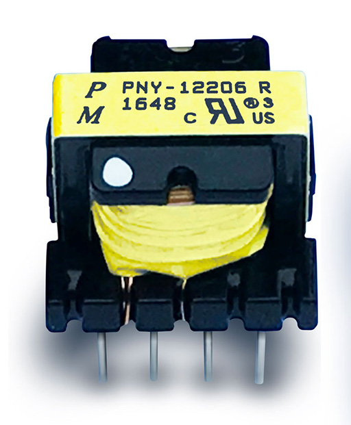
A traditional switching power supply transformer (Fig. 1) consists of primary and secondary wire windings wound on a bobbin and ferrite core. Wire insulation and tape are used to separate the windings. The bobbin and core configuration are determined by the circuit topology.
Figure 1. Here’s an example of a bobbin and core transformer for a 100-kHz switch-mode power supply.
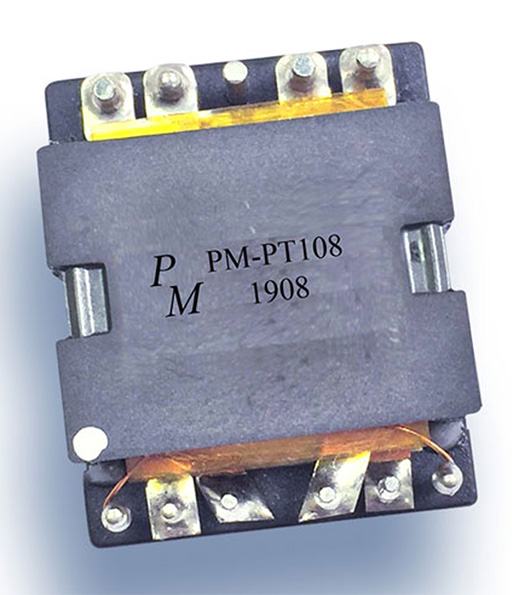
A planar magnetics transformer (Fig. 2) replaces the wound wire and bobbin with thin copper sheets “wound” on a printed circuit board. The PCB is sandwiched between a ferrite core and fastened with rivets.
Figure 2. This is a planar magnetics transformer that’s optimized for switching power supplies operating at up to 700 kHz.

Higher Frequencies = Smaller Magnetics Components?
The first-order effect of the increase in switching frequency is the reduced inductance of magnetic components. As frequencies continue to rise to several hundred kilohertz and into the megahertz range, other factors emerge that can impact the size-reduction benefits of lower inductance.
Of significant importance is skin effect. Skin effect is the tendency of an alternating electric current (ac) to become distributed within a conductor, whereby the current density is largest near the surface of the conductor and decreases with greater depths in the conductor. Since resistivity is a function of the cross-sectional area of the conductor, the result of skin effect is higher resistance at higher frequencies.
This can be resolved, when using a conventional wire-wound-on-bobbin transformer, by increasing the diameter of the winding wire. Another way would be to bundle multiple, smaller gauge wires. Both add more conductive capacity, but they also add to the bulk of the windings. This, in turn, can result in increasing the core size, which results in higher core losses. A planar transformer’s windings, made up of thin copper foil patterns, are less susceptible to skin effect.
Planar Transformer Advantages
The turns in a planar transformer are flat foil patterns on a printed circuit board, which limits the number of turns possible. At the same time, the greater magnetic cross-sectional area allows for fewer turns. And, the flat form of the magnetic core materials provides a larger surface area for power dissipation.
The printed circuit nature of the windings results in a high degree of consistency in spacing between turns and layers. As a result, interwinding capacitance is consistent and winding interleaving allows for reduced ac conduction losses. And, as with any other printed-circuit layout, creepage and clearance spacing is used to meet dielectric breakdown requirements. Taking all of this into account, planar transformers offer excellent efficiency and a high degree of reproducibility.
Traditional Transformer Advantages
Were it not for the demand for higher frequencies, it’s somewhat doubtful that planar transformers would be considered as an alternative to traditional wound-wire magnetics. For all of their apparent benefits, and even in those high-frequency applications, traditional wound-wire transformers still offer a number of important benefits. Planar magnetics take up a great deal more circuit-board footprint than traditional transformers. So, unless power dissipation and/or headroom are major design considerations, then designers will typically go with a standard transformer.
Finally, the turnaround time for traditional transformers will be shorter than for planar devices. Samples can be wound in a matter of days and adjustments can be quickly made to optimize the performance. Planar devices require a printed-circuit layout and tooling for the magnetic core materials. In very-high-volume, higher-power applications, planar devices will provide the higher performance and economical solution. But traditional magnetics will be the answer for nearly every other application.
Working with a Qualified Supplier
Ultimately, the best idea is to work with a qualified supplier who understands the benefits and tradeoffs of both transformer types. That way, designers can be assured of a truly optimum solution.
Source: Electronic Design news
by Dennis Earley, Premier Magnetics
- Space-Grade components available for immediate delivery - April 10, 2025
- Exclusive stock on doEEEt: How to access and request - April 10, 2025
- Managing EEE components for LEO and lower cost space missions - December 17, 2024

2 comments on Conventional vs. Planar Switching Power Transformers