Bypass Capacitor Resonances
- Posted by doEEEt Media Group
- On July 8, 2019
- 0
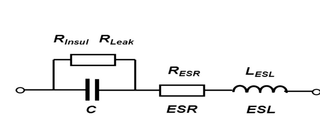
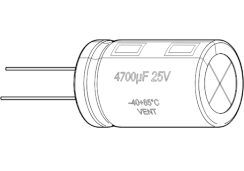
Ideal capacitors only exist in textbooks. Every real-world capacitor has additional complexity arising from its physical structure. Two plates separated by a dielectric layer are in series with wire leads or metal foils through which we make our actual connections. Those two metal conductors introduce an equivalent series inductance or ESL plus an equivalent series resistance or ESR. Taken all together, the physical capacitor is a series tank circuit that has a series resonant frequency and a “Q” of that series resonance which is affected by the series resistance.
It is not just a matter of semantics that a capaciTOR will exhibit an essentially capaciTIVE impedance for electrical excitation at any frequency below that of its series resonance and that it will exhibit an essentially inducTIVE impedance for electrical excitation at any frequency above that of its series resonance.
There is conventional wisdom for broadband rail voltage bypassing which says that you should use parallel combinations of different sized capacitors. The usual line-up is a large value of an aluminum or tantalum electrolytic capacitor, call that C1, in parallel with a large value ceramic capacitor, call that C2, in parallel with a small value ceramic capacitor, call that C3, in parallel with a circuit board’s artwork capacitance, call that C4, in parallel with heaven only knows what else such as harness capacitance and/or semiconductor device capacitance, call that C5.
Always bear in mind that each of those five is not really just a capacitor. Each one is a series combination of a capacitor in series with an inductor in series with a resistor. Taken together, they comprise a series RLC circuit which will exhibit series resonance at a series resonant frequency or SRF where SRF = 1 / ( 2 * pi * sqrt (L * C) ). For a combination of five capacitors connected in parallel as described above, there will be five series resonant frequencies AND there will also be four parallel resonant frequencies which can be sketched as follows.
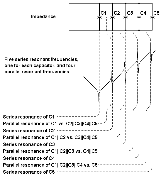
Figure 1 Nine Resonant Frequencies for Five Paralleled Capacitors
The four smaller capacitors C2 thru C5 get into parallel resonances at four frequencies that lie just slightly below their own series resonant frequencies. C1, however, does not show any parallel resonance because that capacitor has nothing inductive with which to create a parallel resonant effect.
Using SPICE and some illustrative numbers, we can delve a bit deeper into the issue as follows.
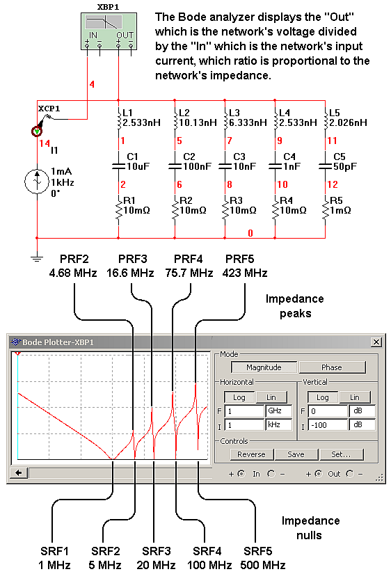
Figure 2 Parallel Bypassing in SPICE, Five Capacitors
For the five capacitances, there will be five series self-resonant frequencies, call them SRF1, SRF2, SRF3, SRF4 and SRF5. Each of the five capacitances will result in an impedance minimum at its own SRF, but, unavoidably, there will also be four parallel resonance peaks of the overall impedance at frequencies PRF2, PRF3, PRF4, and PRF5.
PRF2 arises from the capacitive impedance of the group of C2 thru C5 versus the inductive impedance of C1. Similarly, PRF3 arises similarly from the group of C3 thru C5 versus the pair of C1 and C2, PRF4 arises from the pair of C4 and C5 versus the group of C1 thru C3 and finally, PRF5 arises from C5 versus the group of C1 thru C4.
How deep the five impedance nulls will be and how sharply or broadly peaked the four impedance peaks will be is affected by the resistance values as seen below for just one example. Please note though that the parallel resonant frequencies themselves cannot be entirely eliminated. The parallel resonances will always be there, and you must account for that.
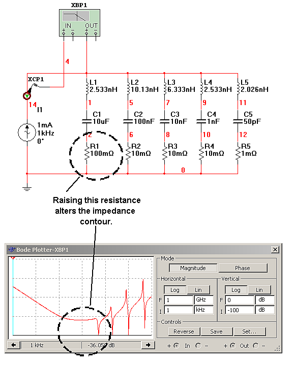
Figure 3 Impedance Curve Alteration by ESR
- Space-Grade components available for immediate delivery - April 10, 2025
- Exclusive stock on doEEEt: How to access and request - April 10, 2025
- Managing EEE components for LEO and lower cost space missions - December 17, 2024


0 comments on Bypass Capacitor Resonances