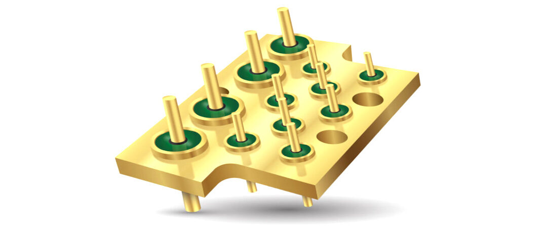
Bulk Head Mounted EMI Filters
- Posted by Tomáš Zedníček
- On February 23, 2020
- 0
Introduction of EMI Filters
End systems are evolving at faster paces and typically involve a common theme where increasingly complex electronic content has to work at faster speeds, in smaller packages, powered by lower voltages. That trend shows little sign of slowing since the sub-components used in creating systems, whether the passive device or active, are shrinking due to improved material purity, new device processing and advances in manufacturing of EMI Filters.
These combined trends create a scenario where EMI has become a huge topic of concern. Compounding that concern is a tendency towards increased government regulations such as the EU EMC directive or FCC EMI requirements or added end customer end threat requirements. With all of this in mind, systems are in huge need of EMI control. Many sub-systems within flight electronics are housed in metal boxes that can essentially be considered a Faraday cage. All that is needed for optimal EMI filtering are bulkhead filters on all the I/O and power lines of those boxes – Faraday cages.
Let doEEEt to make the best component selection for your application
Navigate in our database for free ⇒
Bulkhead filtering provides the ideal EMI noise control since filtering occurs at the box interface thus eliminating concerns over radiation emanating from traces where SMT filters are placed or constructed. Bulkhead Filter Description A Bulkhead filter is a device that mounts into a hole that exists in the system box wall and passes signals from the outside environment through a variety of optional filter types to the internal box environment. See Fig.1.
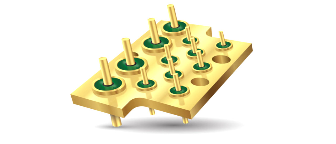
Fig. 1. Typical Bulkhead Filter Wall Mount use Cross Section Bolt in type – upper left / Solder in type – bottom right
EMI Filters or Bulkhead filters either can bolt into the systems box wall or be soldered into the systems box wall. Additionally, arrays of Bulkhead filters can be created that would allow a Bulkhead filter array to be soldered, conductive epoxied or brazed onto a case. Arrays of bulkhead filters are sometimes associated with pogo pins touching the filter pads (in the case of Power/battery charging).
Regardless of the exact form factor, internally the signals on each side of the filter are connected through the filter network. Common filter configurations that exist within the filter can be C, L, T, Pi, LC, CL and transient suppression in functionality. A description of the filter types is below and shown in Fig. 2.
Internal Construction of EMI Filters/Bulkhead Filter
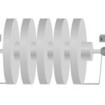
This paper is based upon the use of discoidal capacitors used as the capacitive element – the building block – (C) of the various filter types. An alternative to a discoidal capacitor is tubular capacitors. However, since tubular capacitors exhibit low capacitance ranges and increased failure rates due to mechanical stress – they are not considered in this paper. See Fig. 3 for a discoidal capacitor metallization and how it’s used within a simple bulkhead filter.
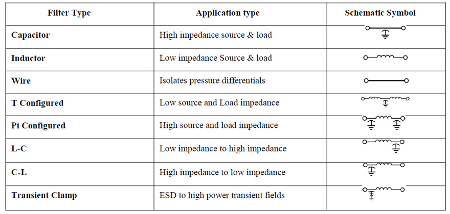
Fig. 2. Filter Types

Fig. 3. Discoidal Capacitor Metallization (left), Bulkhead Filter Cross Section (right)
Discoidal capacitors are a circular form factor device. Discoidal capacitors have an inner metalized hole/termination for one set of electrodes and the outside round edge of the capacitor is metalized to connect the opposing electrode set. The outside metallization is then either soldered or conductive epoxied into place within the plated metal housing of the bulkhead filter. The ceramic dielectric of the discoidal capacitor can be based upon any dielectric however; this paper considers NPO/C0G and X7R dielectric based products.
The inductors used in bulkhead filters can range from ferrite beads to magnetic core and wire wound devices. Once the internal design of the filter has been completed and the filter is electrically assembled, the internal components are then isolated from the outside environment using either epoxy resin (for non-hermetic parts) or a glass seal (for hermetic parts). A combination of epoxy/glass can be used if one end of the filter is needed to be hermetic.
The resin is selected by its compatibility to the internal components CTE as well as its ability to seal the internal filter from effects of external moisture in the use environment. Epoxy provides enhanced shock & vibration characteristics since it acts to cushion and hold the internal filter components in their original positions. Unlike resin-filled filters, hermetic devices have a glass to metal seal soldered onto the metal housing to provide zero possibility of outgassing and to provide the highest level of environmental isolation between internal filter components and the outside world.
Regardless of the type of filter used – hermetic or resin filled – care must be taken to not adversely affect the filter by excessive torque or heat when installing. Excessive torque can deform the metal housing & impart stress to the ceramic thus causing cracks on the discoidal capacitor in the case of resin-filled filters. Excessive torque on hermetic case filters can break the devices hermetic seal and cause cracks in the ceramic discoidal capacitors as well.
When properly selected and installed, bulkhead filters provide high-reliability operation and the highest attenuation filter responses. The use of bulkhead filters represents a best-case control method of EMI because attenuation occurs at the Faraday cage (case or frame wall) rather than after the signals enter the case. Filtering within the case wall does nothing for controlling signals radiated off or conducted onto lines prior to the PCB based filter.
In addition, the parasitic content of the discoidal capacitors is greatly lower than that of discrete capacitors used on a PCB. Therefore the electrical response of filters is based upon nearly ideal capacitors – discoidal capacitors with low parasitic loss greatly eclipses filters based upon discrete passive components placed on a PCB in any of the filter types previously stated. Not only is the package inductance of the MLCC higher relative to the discoidal but the trace dimensions and SMT pads add considerable inductance.
Those higher parasitic inductances and capacitances limit the frequency response of any filter based upon discrete passive devices. Depending upon the case size, discoidal capacitors can exhibit inductance 1/20 that of MLCCs.
Filtering size reductions
The needs for smaller lighter filters is easy to understand given that the cost of launching 1 pound of hardware is approximately $10,000. With this in mind, weight and volume reduction is key to future systems performance BUT these reductions cannot come at the expense of filter capability, throughput current rating or reliability. Two simple methods exist to increase filter density on a box wall.
- The most obvious is to use round head filters vs. those with hex head configurations. Round head filters need virtually zero clearance for assembly & torquing relative to hex head filters. Round head filters can be tightened with modified tools on the vertical axis of the filter. Though this will not reduce the overall volume or weight of filters – it would allow tighter packing on I/Os and a potential end higher box density.
- The next option is to consider custom filter plate assemblies that utilize round case filters fitted into custom steel, brass or aluminum plates designed for maximum density and minimum stress to the individual filter. Assemblies allow end users to receive finished high-density filters that have been torqued, soldered and tested prior to shipment.
A comparison between Hex head filters, round head filters, and custom plate assembly is shown in Fig. 4.
In order to achieve true weight and volume reductions – miniaturization of filters must be utilized. Miniature bulkhead filters are specially designed for a reduction in mass/volume over traditional filter types. The various miniature filter families are based upon the smallest discoidal capacitors available as well as size-reduced inductors. The miniaturization trends of bulkhead filters can be grouped into three families – miniature, sub-miniature and microminiature.
A comparison of weight, volume, type, and range is shown in Fig. 5.
Regardless of the specific family chosen, the volume and mass of miniature classes of filters are spectacular even when compared to discrete SMT capacitors. For example, a 0805 MLCC weight is approximately 0.020 grams and occupies 0.0049 ccs.
If PCB pads and ’keep out’ rules were added to the 0805 discrete capacitor example, the total volume used would nearly double (~ 0.0085cc) and the filter response would be possibly 10% as efficient as a bulkhead mounted filter. Note – the efficiency estimate depends upon a complex weighing of frequency response needs and routing impacts. This number is somewhat subjective and could vary greatly depending upon end designs.
Having established the range, mass and volume characteristics of miniature filters, attention should be paid to these filters attenuation across frequency. The insertion loss requirements of a C type filter of 1nf value called out in MILPRF-28861/12 are shown in Fig. 6. Regardless of physical size – standard, miniature, sub-miniature, and microminiature meet or exceed the attenuations in the table.
An additional comparison has taken place to determine the ESD survivability of Bulk Head mounted FeedThru filters. A set of tests using the human body model (HBM) of 150 pF, 330 ohms, and contact discharge has been completed. This test has a 10 Hz repetition rate of alternate polarity pulses. A total of 10 pulses of varying magnitude were injected into the center pin of the filter. Zero failures were found within C type filters of 10pf, 100pf and 1000pf at the test level currently completed – 8kv. Additional work is being conducted to determine maximum voltage survivability and
repetitive strike wear out.
Predictions of Future Bulkhead Filters
Bulkhead will continue to reduce in size but eventually will hit a wall of practical size limits. That limit will be dependant upon the level of capacitance packaged within miniature discoidal. At some point, the amount of electrode pull back from exterior ceramic walls will be greater than the active area of the disciodal. Further size reductions would dramatically reduce discoidal capacitance values.

Fig. 4. Hex Head (left), Round Head (center), Custom Plate Filter Assembly (right)
| wdt_ID | Filter Type | Dia. mm | Max Cap nf | Current | Voltage | Frequency | Weight g | Volume cc | Configuration |
|---|---|---|---|---|---|---|---|---|---|
| 1 | Miniature Solder in | 3.05 | 50 | 5 amp | 200 v | 100mhz - 10 Ghz | 0.0948 | 0.0204 | C, L |
| 4 | Miniature Bolt in | 2.67 | 27 | 5 amp | 200 v | 10mhz - 10Ghz | 0.1434 | 0.0225 | C, L, Pi |
| 7 | Sub-miniature Solder in | 2.67 | 27 | 2.5 amp | 200 v | 10mhz - 10 Ghz | 0.0796 | 0.0145 | C, L |
| 10 | Sub-miniature Bolt in | 2.18 | 5 | 3 amp | 200 v | 10mhz - 10 Ghz | 0.0902 | 0.0139 | C, L, Pi |
| 13 | Micro-Miniature Solder in | 1.90 | 5 | 1.5 amp | 200 v | 10mhz - 10 Ghz | 0.0336 | 0.0056 | C, L |
| 16 | Micro-Miniature Bolt in | 1.85 | 5 | 3 amp | 200 v | 10mhz - 10 Ghz | 0.0591 | 0.0097 | C, L, Pi |
Fig. 5. Comparison of Miniature, Sub-Miniature and Micro-Miniature Filters
Up until that point, size reductions are taking place and a parallel effort to increase current capacity, voltage and operating temperature ranges will take place. Additional work is being done on devices able to work over higher pressure ranges and across the higher/wider frequency spectrum. New configuration pins will emerge which will optimize connections in specific applications. Families of new component types will be packaged within the filter to essentially create bolt in/solder in flight-qualified modules.
Summary
Bulkhead mounted filters have experienced a decrease in size from what is thought of as the state of the art device. This size reduction was made possible by miniaturization of the discoidal capacitor – the fundamental building block of bulkhead filters.
Significant mass and volume reductions are possible when considering Miniature, sub-miniature and micro-miniature filters. The filter performance was not negatively affected by the size reduction to miniature packages.
Likewise, Electrical overstress ability was maintained in miniature filters. Size reduced filters hold great promise in next-generation flight electronics.
| wdt_ID | Filter Type | Value (pF) | 1 Mhz | 10 MHz | 100Mhz | 1Ghz | 10Ghz |
|---|---|---|---|---|---|---|---|
| 1 | C | 1000 | --- | 4 | 20 | 31 | 55 |
Fig. 6. 1nf C type Filter MIL-PRF-28861/12 Attenuation Requirements
source: EGGO Space s.r.o ; ESA SPCD 2018 Symposium
EPCI e-symposium library article, published by EPCI under the approval of ESA SPCD 2018 organizing committee.
- Why low ESR matters in capacitor design - May 24, 2021
- Voltage and Frequency Dependence on Resistors - March 6, 2021
- Permeability concept in Inductors - March 4, 2021


0 comments on Bulk Head Mounted EMI Filters