High-Temperature Applications Resistor Guidelines
- Posted by doEEEt Media Group
- On May 5, 2021
- 0
Tom Morris, Field Applications Engineer, Sensors and Specialist Components, at TT Electronics discuss a selection of resistor technologies for high-temperature applications.
Until recently, the limiting factor in high-temperature electronics has been the degradation in semiconductor properties of the active components used. However, with recent advances in high-temperature semiconductors and silicon-carbide-based materials, passive components such as resistors have been the limiting factor. As a result, proper resistor selection has become a critical factor in the design of high-temperature electronics to ensure proper operation and reliability.
Resistors have traditionally been manufactured by a variety of methods and technologies, including metal and metal-oxide film, metal foil, carbon, wirewound, and thick-film methods. Each has specific characteristics that make them more or less suitable for high-temperature applications. Resistor degradation at a high temperature can vary from a small resistance change over time to a catastrophic change in resistance, exhibited by either becoming open circuit or, in some cases, a short circuit.
Wirewound Resistors
Although the thought of as a mature technology, many wirewound resistors actually fare quite well in high-temperature applications up to ambient temperatures of 200 to 250°C and above. Of relatively simple construction, wirewound resistors are made by winding a resistance wire (such as Nichrome, which has very good high-temperature characteristics and is often used in heating elements), onto an alumina or steatite ceramic core, and welded to metal end caps press-fit onto each end.
The resistor is typically insulated and made weatherproof by encapsulating the unit using vitreous enamel (glass), silicone, cement, or epoxy compound. The encapsulation material is often the “weakest link” and can be the source of failure at high temperatures. This can be the result of a difference in thermal expansion coefficient causing cracks in the coating and allowing humidity or moisture ingress, initiating stresses on the underlying wire, or due to decomposition or degradation in its insulating properties at high temperature. As a result, epoxies generally aren’t best suited for long-term high-temperature applications, but silicones and vitreous enamel materials function well.
Vitreous enamel-coated resistors create a near hermetic package and provide additional protection in hazardous environments that occasionally can be associated with high operating temperatures, especially in the oil and gas industry. One caveat, though, is that the bulk resistivity of the enamel-coating material tends to drop significantly at high temperatures, and it’s been known to affect the overall installed resistance as the insulation properties are significantly reduced with increasing temperature.
The high-temperature stability of vitreous enamel-coated wirewound resistors is quite good, exhibiting resistance changes of around 1-2% upon exposure to 200°C for 1000 hours, with typically larger changes for other wirewound resistor types. One downside to wirewound resistors is their limited upper resistance range, inherently associated inductance (although this can be greatly reduced by specifying a non-inductive “Ayrton Perry” winding, which essentially winds two wires in opposite directions around the core to cancel inductance), and their relatively large size. As a result, other resistor types hold more promise for high-temperature operation.
Thick-Film Resistors
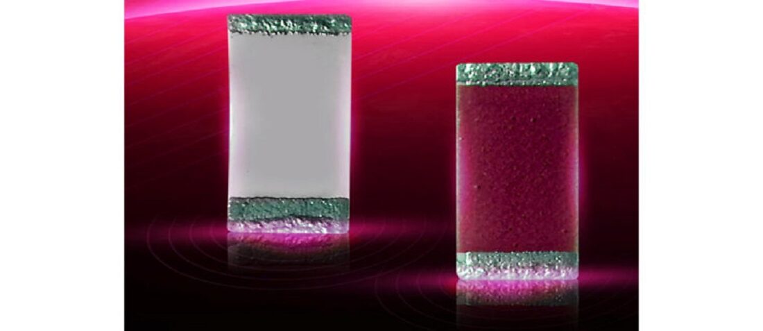
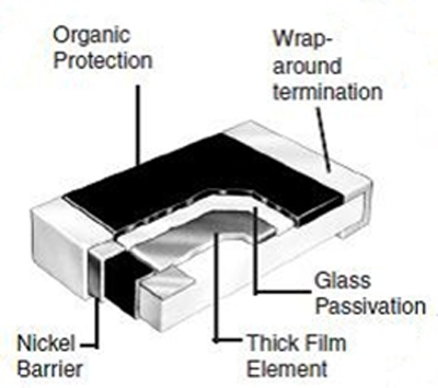
Thick-film resistors have received a significant amount of attention for high-temperature applications in recent years. These resistors are made by depositing a blend of metal and particles onto a ceramic substrate and firing at a high temperature (typically 850°C or so in the air) which creates a conductive cermet matrix. Thick-film conductor formulations for high-temperature use are typically gold, palladium-silver, or platinum-silver (Fig. 1). After laser trimming to value, a layer of glass insulator is often applied on top for environmental protection. Thick-film resistors can be made quite small, routinely down to 0201 or smaller in surface-mounted sizes.
Because the initial processing temperature for thick-film resistors is quite high, this technology holds excellent promise for future developments of high-temperature applications. Testing of special high-temperature thick-film resistors manufactured by TT Electronics show less than 0.25% average resistance change after 1000 hours (no load) at 300°C (Fig. 2).
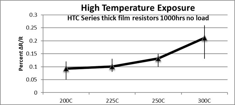
Fig. 2. The effects of high-temp exposure are demonstrated by 1000-hr no-load resistance change (HTC series, 0805 size, 180 kΩ, 20 pcs).
For operation at high temperatures, traditional solders aren’t an option (typical lead-free solders have a liquidus temperature of approximately 221°C), so other methods of attachment including wire bonding, high-lead-content HMP solder (often Sn05Pb93.5Ag1.5-296°C), or conductive adhesives are used. As a result, it’s necessary to select the termination materials compatible with the attachment method. This usually requires gold terminations for wire bonding or conductive adhesives, polymer silver, Pd-Ag or Pt-Ag for conductive adhesives, and plated materials with a nickel underlayer for HMP solders.
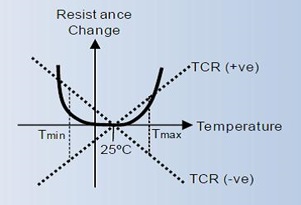
For thick-film resistors, the typical temperature coefficient of resistance (TCR) is approximately ±100 ppm/°C over normal temperature ranges, but it can be (and often is) dramatically nonlinear as the temperature deviates from normal ranges (Fig. 3). However, even if we assume a TCR of 100 ppm/°C, operation at 200°C above ambient can result in a perceived resistance change of as much as 2% simply due to the temperature excursion—and possibly much more depending on the actual TCR characteristics at higher temperatures. As a result, more precise applications may require thin-film networks or wirewound resistors.
Thin-Film Resistors
Unlike thick-film resistors, which are characterized by an additive high-temperature manufacturing process, thin-film resistors are typically manufactured using a subtractive, sputter deposition process. Subsequent manufacturing operations are used to condition the resistor films to optimize high-temperature performance. Thin-film resistors are typically characterized by low TCR, precision performance, and often available in networks or packages with more than a single resistor.
The thin-film resistor material of choice is typically either a nichrome alloy or tantalum nitride. Both of these materials (see table) tolerate high melting points, which tend to result in less microscopic grain growth at high temperature and are highly resistant to oxidation—two potential sources for significant resistance change at high operating temperatures.
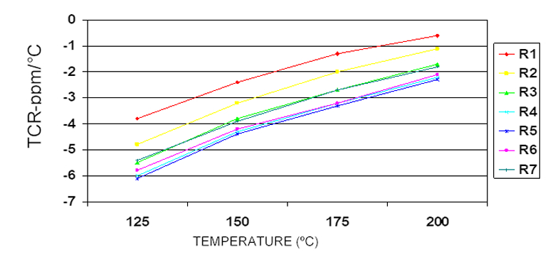
Both resistor films offer good resistance stability and excellent low TCR at normal operating temperatures which carry over to some extent at high-temperature operation. In addition, they both possess a relatively linear TCR curve over a wide temperature range (Fig. 4). Although the data shown is for a nichrome-alloy metal film resistor, similar characteristics are seen with the tantalum-nitride materials. An additional benefit is illustrated in the graph, which demonstrates the close TCR tracking or matching between the resistors in the common network (in this case, a 7-resistor network).
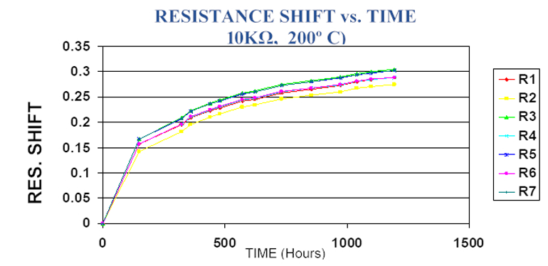
One intriguing aspect of thin-film resistors is that a significant amount of the total resistance change occurs during the first 100 to 200 hours of operation (Fig. 5). Various mechanisms, such as oxidation, migration of metallic layers, or metallic diffusion can cause this resistance change.
However, the rate of resistance change significantly decreases over time, which allows for a marked reduction in the absolute change in resistance over life by subjecting the resistors to a high-temperature bake at or exceeding the temperature that the resistors will be used. This reduction in the resistance change is illustrated in Figure 6, showing a similar resistor network as in Figure 5, but with a 200°C, 148-hr bake added. In this case, the resistance change has been reduced to less than half over 1,000 hours of exposure, dramatically improving overall resistor stability.
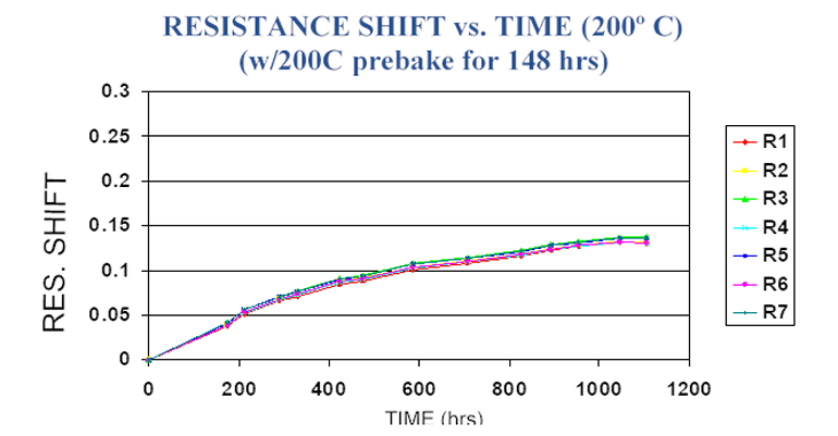
Fig. 6. This resistor network is similar to that as in Figure 5, but with a 200°C, 148-hr bake added. The image depicts a reduction in the resistance change, reduced to less than half over 1,000 hours of exposure, significantly improving overall resistor stability.
Figure 6 also demonstrates another important characteristic: All of the resistors in the common network track each other very well over time and temperature. This makes it possible for very accurate resistor divider and voltage ratio networks to provide excellent performance, even at elevated temperatures.
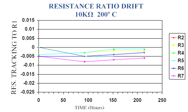
It almost always lowers the cost to specify a resistor network with two or more resistors (of different values) that track each other well, rather than using individual resistors that will give similar tracking and matching performance. Figure 7 illustrates the typical ratio tolerance performance of a high-temperature resistor network—the difference in ratio performance is within 0.005% (50 ppm) over life.
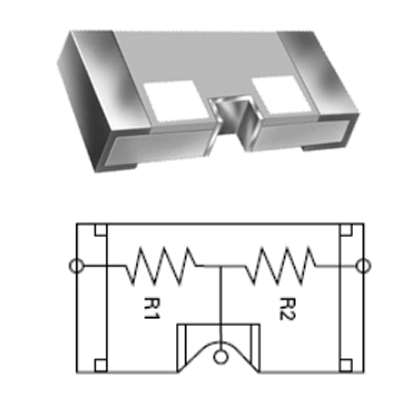
Thin-film resistor networks can be purchased in a variety of package configurations, such as SOT23, SOT147, SOIC, QSOP, BGA in SMT, along with the mature through-hole packages like SIP/DIP configurations. The 3-terminal (2-resistor) 1206 divider package shown in Figure 8 offers outstanding high-temperature performance and excellent resistor tracking over time and temperature. Both gold and solder terminations allow flexibility in the attachment.
Acknowledgements
The author would like to recognize the following people on the TT Electronics Sensors and Specialist Components team for their assistance and information: Stephen Oxley, Sr. Applications Engineer; David Jackson, Sr. Development Engineer; and Mike Torres, Applications Engineer.
References
- J.C. Wendel, P. Hellmold, “Vitreous Enamel A Highly Effective Material Compound,” proceedings of the ECL2 workshop, CERN, Geneva Switzerland.
- Jeffrey E. Naefe, R. Wayne Johnson, “High-Temperature Storage and Thermal Cycling Studies of Thick Film and Wirewound Resistors,” IEEE Transactions on Components and Packaging, March 2002
- Robert C. Weast, Ph.D., Handbook of Chemistry and Physics, 65th Edition.
- Ronald K. Jurgen: Automotive Electronics handbook, 2nd Edition.
- Resistors for Medical Applications, TT Electronics
- Indium Corporation of America Solders, product datasheet.
- Space-Grade components available for immediate delivery - April 10, 2025
- Exclusive stock on doEEEt: How to access and request - April 10, 2025
- Managing EEE components for LEO and lower cost space missions - December 17, 2024



0 comments on High-Temperature Applications Resistor Guidelines