Balancing – Theoretical Background
- Posted by doEEEt Media Group
- On February 9, 2023
- 0
Imbalance of Serial Connected Supercapacitors
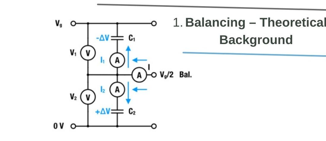
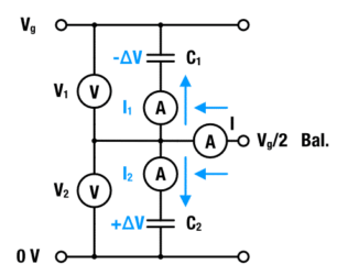
A parallel connection of an R-C unit and an insulation resistance may model a capacitor. We neglect the insulation resistance and consider a series stack of two capacitors with capacities C1 and C2 – see Figure 1.

Figure 1: Two capacitors in series connection and balancing currents in a capacitor stack
The conserved quantity in such a stack is the condensed charge q at the capacitor, i.e. at its internal interfaces. Using the conservation of charge V1,2 = q/C1,2, the voltage drop over each capacitor is:
![voltage drop V1 on two capacitors in series [1]](https://www.doeeet.com/content/wp-content/uploads/2023/02/voltage-drop-V1-on-two-capacitors-in-series-1.png)
voltage drop V1 on two capacitors in series [1]
![voltage drop V2 in two capacitors in series [2]](https://www.doeeet.com/content/wp-content/uploads/2023/02/voltage-drop-V2-in-two-capacitors-in-series-2.png)
voltage drop V2 in two capacitors in series [2]
with Vg = V1 + V2 as the total voltage. If both capacitance values are equal, the voltage at the terminals of two serial-connected capacitors is equal:
![voltage on two capacitors in series with equal capacitance [3]](https://www.doeeet.com/content/wp-content/uploads/2023/02/voltage-on-two-capacitors-in-series-with-equal-capacitance-3.png)
voltage on two capacitors in series with equal capacitance [3]
Thus, the system is balanced and each capacitor is charged at its rated voltage Vr. In the following we may consider the case where C1 is larger than C2. With above equations it can be shown that the voltage drop at each terminal is unequal by:
![voltage drop on two capacitors in series with unequal capacitance [4]](https://www.doeeet.com/content/wp-content/uploads/2023/02/voltage-drop-on-two-capacitors-in-series-with-unequal-capacitance-4.png)
voltage drop on two capacitors in series with unequal capacitance [4]
![voltage drop V1 on two unequal capacitors in series [5]](https://www.doeeet.com/content/wp-content/uploads/2023/02/voltage-drop-V1-on-two-unequal-capacitors-in-series-5.png)
voltage drop V1 on two unequal capacitors in series [5]
![voltage drop V2 on two unequal capacitors in series [6]](https://www.doeeet.com/content/wp-content/uploads/2023/02/voltage-drop-V2-on-two-unequal-capacitors-in-series-6.png)
voltage drop V2 on two unequal capacitors in series [6]
Using the definition of capacitance C = ∆q/∆V with q as charges at the capacitor interface and V as voltage at the capacitor), the above equation may be rewritten as:
![voltage drop V1 on two unequal capacitors in series with ∆q expressed [7]](https://www.doeeet.com/content/wp-content/uploads/2023/02/voltage-drop-V1-on-two-unequal-capacitors-in-series-with-∆q-expressed-7.png)
voltage drop V1 on two unequal capacitors in series with ∆q expressed [7]
![voltage drop V2 on two unequal capacitors in series with ∆q expressed [8]](https://www.doeeet.com/content/wp-content/uploads/2023/02/voltage-drop-V2-on-two-unequal-capacitors-in-series-with-∆q-expressed-8.png)
voltage drop V2 on two unequal capacitors in series with ∆q expressed [8]
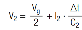
In order to adjust the voltage of each capacitor to Vr = V1 = V2 the charge has to be increased at capacitor 1 and decreased at capacitor 2 by the amount of ∆q. Using the definition of electrical current (I = dq/dt) the voltage may be written as:
![voltage drop V1 on two unequal capacitors in series with I and ∆t expressed [9]](https://www.doeeet.com/content/wp-content/uploads/2023/02/voltage-drop-V1-on-two-unequal-capacitors-in-series-with-I-and-∆t-expressed-9.png)
voltage drop V1 on two unequal capacitors in series with I and ∆t expressed [9]

voltage drop V2 on two unequal capacitors in series with I and ∆t expressed [10]
The current I1,2 is interpreted as the electrical current that has to flow for a time period ∆t to equalize this system. The constant current that is required to equalize a voltage difference ∆V in a given time period ∆t is
![constant current that is required to equalize a voltage difference on two unequal capacitors in series [11]](https://www.doeeet.com/content/wp-content/uploads/2023/02/constant-current-that-is-required-to-equalize-a-voltage-difference-on-two-unequal-capacitors-in-series-11.png)
constant current that is required to equalize a voltage difference on two unequal capacitors in series [11]
Balancing Current and Balancing Time
We may use above equations for the estimation of the current magnitude. In this example we used the full tolerance range of the capacitance, which is 40% (-10%/+30%). Hence, for Cr = 10F we obtain C1 = 13F and C2 = 9F. The total voltage of 5.4V provides then a voltage difference ∆V = 0.49V (i.e. at C2 the voltage drop is V2 = 3.19V and at C1 the voltage drop is V1 = 2.21V). The ∆V ≈ 0.5V is the largest possible imbalance. To illustrate this situation, we use the circuit in Figure 1. The balancing current necessary to balance C1 and C2 within 1 sec respectively according to equation [11] are :

Hence, C1 needs to be charged with I1 = 6.5A and C2 needs to be discharged I2 = 4.5A. The current that has to be provided by the balancing terminal can be calculated with Kirchhoff’s current law. We may consider currents that flow out of the junction as negative and currents that flow into the junction as positive. Since I1 and I2 flow out of the junction and the balancing current I into the junction, the balancing current is:
![]()
Although the result may vary depending on ∆V and ∆t this example of calculation may show that balancing at the characteristic RC-time requires currents of several amperes. The balancing current, required to balance a strongly imbalanced system of ∆V = 0.5V ( as calculated above) in within ∆t can be estimated with:

So far we have neglected the insulation resistance, which starts to dominate the electrical behavior as soon as the SC is fully charged and the charging current becomes smaller than the leakage current Ileak. Most manufacturers specify a measurement time of 72h at rated voltage Vr to determine Ileak. Under these conditions the capacitor may be simply modeled by an ohmic resistance Riso = Vr/Ileak. Hence, if a capacitor is fully charged a serial stack of SC may be considered as a stack of serial connected resistances, which constitute a voltage divider.
- Space-Grade components available for immediate delivery - April 10, 2025
- Managing EEE components for LEO and lower cost space missions - December 17, 2024
- Filtering Characteristics of Parallel-Connected Fixed Capacitors in LCC-HVDC - November 21, 2024

0 comments on Balancing – Theoretical Background