Passive Low Pass Filters
- Posted by doEEEt Media Group
- On November 30, 2020
- 0
There are many different types of filters used in electronics. These filter types include low-pass, high-pass, band-pass, band-stop (band-rejection; notch), or all-pass. They are either active or passive.
In the realm of electromagnetic compatibility, the purpose of a filter is to establish a low-impedance path for RF current to return to the local source of energy, and/or to provide a high impedance to prevent RF currents from flowing on a cable. These so-called EMI filters are often used along with proper shielding to achieve electromagnetic compatibility (EMC) compliance for electrical/electronic products. Undoubtedly, the most useful filter type used in EMC work is the passive low-pass filter.
Passive filters are made up of passive components such as resistors, capacitors, and inductors and have no amplifying elements (transistors, op-amps, etc) so have no signal gain, therefore their output level is always less than the input.
- The Low Pass Filter – the low pass filter only allows low-frequency signals from 0Hz to its cut-off frequency, ƒc point to pass while blocking those any higher.
- The High Pass Filter – the high pass filter only allows high-frequency signals from its cut-off frequency, ƒc point and higher to infinity to pass through while blocking those any lower.
- The Band Stop Filter – the band stop filter is a reversal to the Band Pass Filter and allows signals passing both the lower and higher frequencies either side of the blocking frequency band.
- The Band Pass Filter – the bandpass filter allows signals falling within a certain frequency band setup between two points to pass through while blocking both the lower and higher frequencies either side of this frequency band.
Ideal Filter Response Curves

Fig.1. ideal filter response curves; source credit: Electronic Tutorials
Filters can be divided into two distinct types: active filters and passive filters. Active filters contain amplifying devices to increase signal strength while passive do not contain amplifying devices to strengthen the signal. As there are two passive components within a passive filter design the output signal has a smaller amplitude than its corresponding input signal, therefore passive RC filters attenuate the signal and have a gain of less than one, (unity).
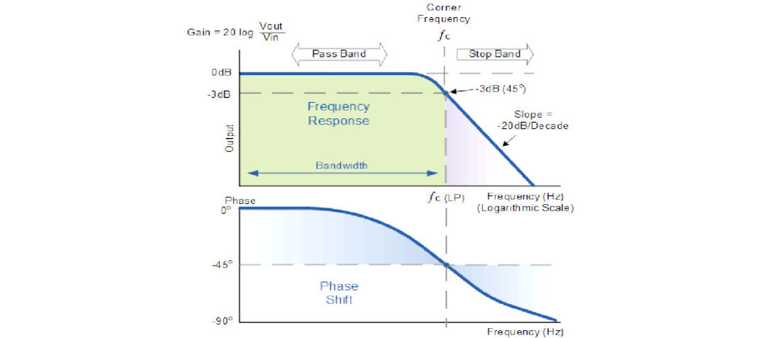
A Low Pass Filter can be a combination of capacitance, inductance or resistance intended to produce high attenuation above a specified frequency and little or no attenuation below that frequency. The frequency at which the transition occurs is called the “cut-off” or “corner” frequency.
The simplest low pass filters consist of a resistor and capacitor but more sophisticated low pass filters have a combination of series inductors and parallel capacitors. In this tutorial, we will look at the simplest type, a passive two component RC low pass filter.
Passive Low Pass Filter
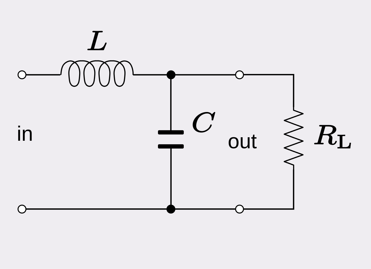
A Low Pass Filter is a circuit that can be designed to modify, reshape or reject all unwanted high frequencies of an electrical signal and accept or pass only those signals wanted by the circuits designer. In other words, they “filter-out” unwanted signals and an ideal filter will separate and pass sinusoidal input signals based upon their frequency. In low-frequency applications (up to 100kHz), passive filters are generally constructed using simple RC (Resistor-Capacitor) networks, while higher frequency filters (above 100kHz) are usually made from RLC (Resistor-Inductor-Capacitor) components.

Fig.2. first order RLC low pass filter circuit diagram, credit source: wikipedia
RC Low-Pass Filter
A low-pass filter is a filter that allows signals with a frequency less than a particular cutoff frequency to pass through it and depresses all signals with frequencies beyond the cutoff frequency. The most basic type of low-pass filter type is called an RC filter, or an L-type filter because of its shape, with the resistive element in the signal line and capacitor placed from line to chassis, these two circuit elements form the shape of an inverted L.
In an RC low-pass filter, the cutoff frequency occurs at resonance, where the capacitive reactance (Xc) equals the resistance (Xc =1/2πfC, or 1/wC, w = 2πf). Sometimes the resistor is not required and just a single capacitor placed across a line to reference ground without a resistor installed may be all that is required to suppress any unwanted noise. A device that presents the circuit with a high AC impedance, while at the same time not affecting signal quality can be used in situations where the voltage drop across the series resistor cannot be tolerated. This device is called a ferrite bead. In addition to their frequency limitation, ferrites can also become easily saturated when there is too much DC current present in the circuit. Ferrites are ineffective if they are saturated and if DC current is too high, using a ferrite as an element in the low-pass may not be an option. Also, depending on how high the impedance is of the source or load requiring filtering, ferrites may not work because they are considered low-impedance and won’t work if circuit impedance is higher than their impedance.
Basic Filter Topologies
Besides the L-type passive filter, there are a couple of other basic filter configurations. These multi-element filters are useful in situations where the range of frequencies involved is too large and impossible for a one component filter to fully attenuate successfully or the signal is too high in amplitude and that one filter element does not provide enough attenuation. Adding a second reactive component will increase the roll off to 12 dB/octave or 40 dB/decade. These types of filters are called various names such as double-pole, two-stage, two-element, or second-order filters. Filters with three reactive components will provide 18 dB/octave or 60 dB/decade attenuation. Four reactive component filters will provide 24 dB/octave or 80 dB/decade attenuation and so on.
Also, different filter shapes are used depending on source and load impedances of the circuit requiring filtering. These different types are used for impedance mismatching between circuit source and load input and output impedances and filter input and output impedances. Like the L-type filter, these other two types are both are named after their visual shapes on circuit diagrams. The first is the π-filter and the second is the T-filter low-pass filter.
Π Filter
The π low-pass filter looks like the Greek letter π. It has a capacitor from the line to be filtered to return, an in-circuit series element (resistor, inductor or ferrite), and then another capacitor from line to be filtered to return.
T Filter
The T low-pass filter looks like the letter T. It has an in-circuit element (resistor, inductor or ferrite) installed on the line to be filtered, a capacitor installed line to return, and then another in-circuit element (resistor, inductor, or ferrite).
Impedance Mismatching
As eluded to earlier, both source and load impedances must be considered in selecting the proper filter configuration (L, π, or T). If you are trying to install a low-pass filter into a circuit in order to suppress unwanted emissions and determine that it is not solving the problem then be sure to check that an impedance mismatch exists. A high-impedance series component should face a low-impedance (i.e. capacitor) and vice versa. You may be asking yourself “What is considered low-impedance and what is considered high-impedance?” In general, impedances of less than 100 Ω are considered low and impedances greater than about 100Ω are considered high.
Selection of the cut-off frequency (fco)
It is important to also ensure that by adding a filter’s impedance to a circuit that it does not, in turn, create a signal integrity problem. In order to ensure this does not happen, be sure to select a cut-off frequency for the filter that does not also attenuate the intended signals used in the circuit. In order to prevent this issue from occurring, try to maintain at least the 5th harmonic of the intended signal (10th harmonic is ideal).
Differential Mode (DM) and Common Mode (CM) Noise Currents
DM signal currents are those out-of-phase currents which transmit intended data whereas CM signal currents are in-phase deliver no valuable data what-so-ever. Although they are much lower in amplitude than DM currents, CM currents are the main causes of regulatory radiated and conducted emissions testing issues.
In a perfect world, DM signals move along one side of a circuit track, and an equal and opposite DM signal moves back on the other side of the track. In order to prevent DM to CM conversion to occur, PCB layout must be perfect and no circuit discontinuities can exist. This ensures that complete canceling of the DM signals occur and no CM current is developed.
If suppression of DM noise is required then placing capacitors across the outgoing and return lines and/or an inductor in series with either outgoing or return line can be employed. This is called DM filtering. If installing a DM filter does not solve the noise problem, then the source of emissions may instead be CM noise.
CM signals are signals that exist in both outbound and return tracks of a circuit. Because they are in-phase, they do not cancel each other but add up substantially enough to cause EMI issues. Because CM noise is present line-to-ground. CM filtering often involves placing capacitors across each signal line to a ground reference. and sometimes also using a CM inductor in the circuit. Any CM inductors placed into the circuit only act on the CM signals that are present, they do not affect the DM signals. If installing a CM filter does not solve the noise problem then the source of emissions may instead be DM noise.
Parasitics
When attempting to utilize a low-pass filter for EMI suppression it is imperative to also consider the non-ideal behavior of the components which make up the filter. Actual passive filter components such as a capacitor also contain some inductance and an inductor contains some capacitance. These parasitic elements of capacitors and inductors limit their useful bandwidth. For example, the reactance of a capacitor decreases until it reaches its self-resonant frequency as frequency increases. Above its self-resonant frequency point, the capacitor becomes inductive and it acts as an inductor because of the parasitic inductance found in its metal plates. A similar situation occurs in inductors. These parasitic effects are greater in leaded types of capacitors and inductors than with the surface mount technology (SMT) types that have almost no lead length.
Layout and Placement Concerns
Proper layout and placement can become the critical factor when attempting to effectively utilize passive low-pass filters for EMI suppression. Longer than necessary trace lengths add extra inductance and impedance which compromise the effectiveness of the filter similar to what occurs as described above regarding parasitics. It is, therefore, crucial to keep connections short. This means placing filter components as close as possible to the circuit to be filtered and not overlooking the length of the return trace. Locating the filter some obscure location far away from the offending signal source is not ideal in most situations.
In addition to keeping connections short, be observant of trace or wire routing that permits too much capacitive and inductive coupling to other noisy signal or traces. To prevent this crosstalk issue from occurring, place filter components right at the entry connector (I/O and power inputs). Placement of a filter deeper inside a circuit or system is just asking for trouble. When proper separation is not maintained, input and output sections are bypassed and the filter is no longer effective. As with a lot of problems encountered in EMC design and troubleshooting, do not rely on the ground as being the ultimate zero-ohm impedance path and sink for noise. It is far better to understand the path of current flow and to keep loop areas small.
References
- Archambeault, PCB Design for Real-World EMI Control, Kluwer Academic Publishers, 2002
- Frenzel, Jr., Principals of Electronic Communications Systems, Fourth Edition, McGraw-Hill, 2016
- André & Wyatt, EMI Troubleshooting Cookbook for Product Designers, Scitech Publishing, 2014.
- Montrose, EMC Made Simple, Printed Circuit Board and System Design, Montrose Compliance Services, Inc., 2014
- Armstrong, “EMC Filters Guide,” Interference Technology, 2017
- Montrose, Printed Circuit Board Design Techniques for EMC Compliance – A Handbook for Designers, 2nd Edition, 2000.
Source: In Compliance article, Electronics Tutorial article
More information on various filter types may be found at Electronics Tutorials or through the other references listed below.
Featured image: frequency response of a 1st-order Low Pass Filter; credit source: Electronics Tutorials
- Space-Grade components available for immediate delivery - April 10, 2025
- Exclusive stock on doEEEt: How to access and request - April 10, 2025
- Managing EEE components for LEO and lower cost space missions - December 17, 2024


0 comments on Passive Low Pass Filters