Optical Amplifier Technologies for Space Applications
- Posted by Enrique Cordero
- On May 7, 2020
- 0
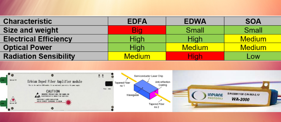
Photonic technologies have been considered for the handling of digital or microwave signals telecommunication satellite sub-systems. They are expected to bring significant improvements and/or constitute one of the critical technologies enabling the practical implementation of advanced payload concepts. They may offer substantial benefits in the development of future telecom payloads with broad bandwidth, extensive connectivity, and enhanced flexibility at low mass and small size.
Most of the existing Optical Amplifier (OA) technologies and currently, products developed for discrete amplifier applications are based on the following categories:
- Erbium-Doped Fibre Amplifier (EDFA),
- Erbium-doped Waveguide Amplifiers (EDWA),
- Semiconductor Optical Amplifiers (SOA).
The different Optical Amplifier Technologies have been reviewed concerning their capability to meet the requirements of onboard space applications and to their suitability for use in space.
EDFA’s
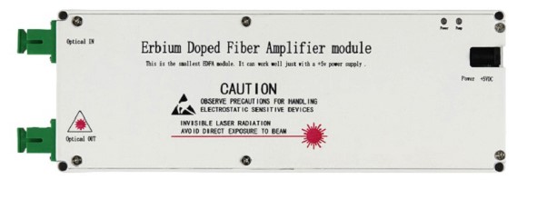
ETFA’s are the most used amplifiers. They can provide all the targeted output powers from +18 to +28 dBm, feature low noise figure (< 5 dB) with typical optical power efficiencies in the range of 30-40 %. They can be designed either with almost no polarization dependence or with polarization maintaining capability. One major drawback wrt the other technologies remains its size and the sensitivity the erbium-doped fiber to TID. These optical amplifiers can today provide a first solution to the needs for moderate power amplifiers when the radiation environment is low (<40 Krad), this the significant critical aspect being their behaviour in the space environment.
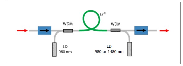
The basic layout of an EDFA is shown in the figure below. As mentioned previously, the Erbium is excited into population inversion by pumping with laser diodes at either 980 nm or 1480 nm, or both.
EDWA’s
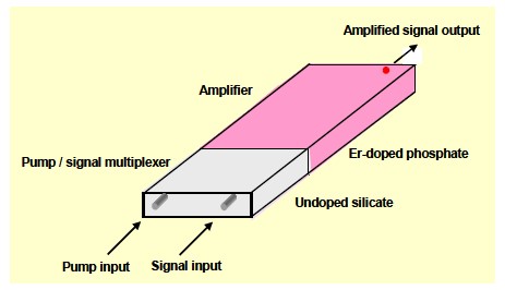
The principle of Erbium-doped-waveguide-amplifier (EDWAs) is, in essence, equivalent to Erbium-doped fibre amplifiers (EDFA). The difference is that the optical amplification takes place inside an optical waveguide integrated on a planar substrate rather than inside an optical fibre. An EDWA consists of a waveguide embedded in an amorphous erbium-doped glass substrate as shown on next figure.
EDWAs require high doping levels of the glass substrate, to achieve high (up to 14dB) amplification in rather short waveguides (< 10 cm). Usually, these glass substrates are aluminium silicate or aluminium phosphate. While the use of aluminium glass as a substrate may have little relevance on Earth, it increases the device radiation susceptibility and thus could reduce its use in space.
SOA’s
Semiconductor Optical Amplifiers (SOAs) are considered as a potential alternative to EDFAs, in applications where the requirements on performance are less stringent, and factors like integration or the need for amplification in an extended range of wavelengths, like in coarse WDM, come into the picture.
The motivation for Semiconductor Optical amplifiers includes their small size and potentials for further integration with other active functions on a semiconductor substrate. They provide a low-cost and size reduced effective amplifier solution in terrestrial telecom networks. Still, they are a key technology for other functions including all-optical wavelength conversion, wavelength selection, fast gating and mid-span spectral inversion.
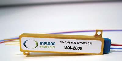
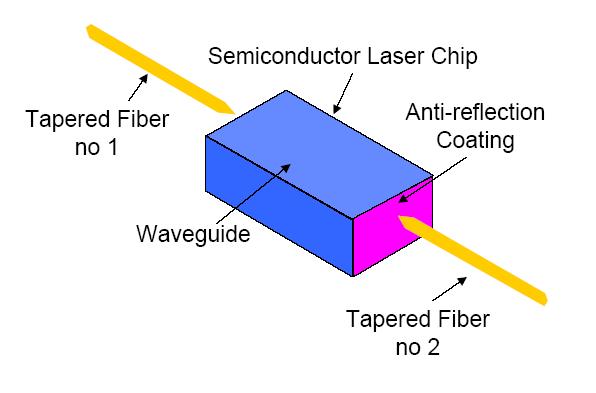
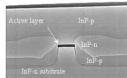
A semiconductor optical amplifier (SOA) is essentially a laser diode without oscillation. A typical architecture of an SOA is shown in the figure. It is based on the same technology as Fabry-Perot (FP) laser diodes but without end mirrors and with fibre attached to both ends. Its operating principle is based on stimulated emission from injected carriers in an InP chip. It amplifies any optical signal that comes from either fibre and transmits an expanded version of the signal out of the second fibre. However, there are two main conditions for an SOA; first, it must be biased just below oscillation threshold, and second, it must include a low facet reflectivity (Anti-Reflection (AR) design at the end faces) to avoid cavity resonance and prevent the device from acting as a laser.
The wall plug-efficiency is today limited by TEC consumption. Operation without TEC is possible but would probably compromise the performance. Integration of SOA within an array that shares the same TEC is another option, but so far, the combination has also led to performance degradation.
The main advantage of the SOA amplifier is its stability and low degradation in the radiation environment, and it reduces size.
- Component Testing for New Space Applications - July 2, 2021
- Optical Amplifier Technologies for Space Applications - May 7, 2020
- Cryogenic Testing of EEE & Electro-Optical components - September 21, 2019


0 comments on Optical Amplifier Technologies for Space Applications