DC-DC Converters
- Posted by Tomáš Zedníček
- On June 7, 2019
- 0
Capacitors
Today, one can hardly find a consumer, industrial or high-reliability electronic device that does not make use of a voltage regulator. Designers basically use two types of regulators, linear LDO (low dropout) and step-down switch-mode DC/DC regulators to convert the voltage to lower level. Switching DC-DC regulators are preferred for applications that require a greater difference between input and output voltages because they are more efficient in such operating conditions.
Switching DC-DC Power Regulators
Switched-mode power supplies (SMPS) are commonly found in many electronic systems. Important SMPS requirements are a stable output voltage with load current, good temperature stability, low ripple voltage, and high overall efficiency. One key component in switching power systems is the output capacitor – used to store the charge and for smoothing and therefore its careful selection plays a vital role in determining the overall parameters of the power supply.
There are typical SMPS topologies shown in Figure 1.
SMPS are used for VIN-to-VOUT transformation:
- VOUT > VIN, realized by step-up, flyback or SEPIC converters,
- VOUT < VIN, realized by step-down, flyback or SEPIC converters,
- VOUT = VIN, realized by flyback or SEPIC converters,
- VOUT = -VIN, realized by an inverting converter.
An SMPS circuit consists of these specific parts:
- one or more switching transistors, mainly enhancement-mode MOS-FETs,
- input and output smoothing capacitors,
- low-loss passive device(s) accumulating electromagnetic energy (inductors, capacitors, transformers),
- non-linear rectifying devices (plain P-N or Schottky diodes),
- control sub-circuit for switching transistor management, feedback stability, and shut-down functionality.
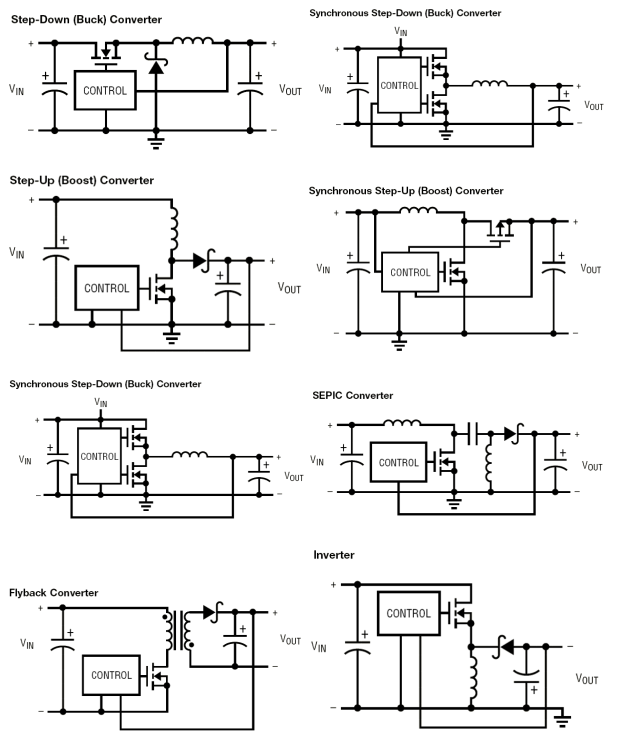
Figure 1 : Typical SMPS topologies:
a) Step-down (buck) converter; b) Synchronous step-down (buck) converter
c) Step-up (boost) converter;d) Synchronous step-up (boost) converter
e) Synchronous step-down-up (buck-boost) converter; f) Single ended primary inductor converter (SEPIC)
g) Flyback isolated-output converter; h) Inverting converter (inverter)
Capacitor Requirements
Input Capacitors
The main purpose of the input capacitors is RF noise suppression and energy reserve. Various capacitor technologies can be used per the application conditions mainly:
- DC-DC source coupling
- DC-DC source impedance
- DC-DC source loading
- switching frequency
The most of application may be occupied today by MLCC capacitors, some attention has to be paid by a selection of the right capacitance value due to the drop of capacitance with DC voltage and small AC ripple. Aluminum capacitors could be used for larger consumer and industrial applications, where larger physical size may not be of concern. Attention has to be paid to the maximum allowed ripple current per the ESR / type of the aluminum capacitors, usually lower ESR type may be more suitable. Tantalum solid capacitors with MnO2 may not be generally recommended for the input side due to the spike surge current and risk of thermal runaway. Polymer tantalum capacitors may be more suitable to use.
Output Capacitors
The main purpose of the output capacitors is to provide RF noise filtration, voltage and current ripple suppression and function as a local energy reserve for the load. Important application conditions to review for the capacitor selection guide are:
- local character and sink value
- storage inductor value
- converter switching frequency
- ESR and ripple demands (achievable by single or more caps in parallel)
The general requirements for output capacitors are then:
- Low ESR
- High Capacitance
- Low ESL
- Capacitance and ESR temperature, voltage and frequency stability
The recommendation for output capacitors would be similar to that for input capacitor with one difference – the actual surge current load is usually very well stabilized through the feedback loop of the converter, thus the surge current is limited. It is thus safe to use capacitor technologies that are more sensitive to surge load such as tantalum capacitors with MnO2.
LDO Low Drop-Out Regulators
There are two functions of a capacitor connected to an output of LDO:
- Local electrical energy reserve
- RF noise coupling to ground
- Feedback stability factor for LDO
Simplified structure of LDO with external input/output capacitor and feedback resistors is shown in Figure 2.
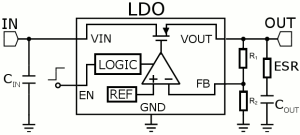
Figure 2: Simplified LDO and typical external components
It is commonly known that the output capacitor influence the gain & phase margin of the LDO loop and thus the stability of the LDO see Fig.3. The output capacitance and ESR value with a connected load and its parameters are of the critical importance for the LDO operation.
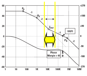
Fig.3. LDO phase and gain stability window that has to be maintained by ESR of the output capacitor
The capacitor’s ESR was the main limitation especially in the case of older LDO circuits where too low ESR of MLCC capacitors could not be used with LDO. The new LDO generation has improved dramatically stability of the loops and it can be said that even MLCC capacitors can be used with LDO now. Nevertheless, it is of importance to check the LDO datasheet for the defined capacitor’s ESR working range. It has to be also noted that the ESR stable operation range has to maintained under all environment conditions – it means to count with its stability with temperature, moisture, etc.
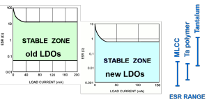
Fig.4. ESR stability window comparison between the older and newer LDO generation.
Save time searching the EEE components of your design in doEEEt database.
- Why low ESR matters in capacitor design - May 24, 2021
- Voltage and Frequency Dependence on Resistors - March 6, 2021
- Permeability concept in Inductors - March 4, 2021



0 comments on DC-DC Converters