Hardware and Software Design
- Posted by Mario Rueda Aguilocho
- On March 31, 2022
- 0
Attending to the official definition, Electronic design (Hardware and Software design) involves selecting and interconnection physical devices in various topologies to meet performance specifications, environmental requirements and cost budgets, operating life requirements, and other design constraints in agreement with an overall schedule.
Nowadays, electronics are everywhere, and if there are any electronics contents, there are electronics engineers to design those electronics circuits.
Understanding Hardware and Software Design
Modern electronics started with the invention of the vacuum diode, which later evolved into triode, tetrode, and pentode tubes with the possibility of amplifying signals.
Later, the junction transistor was invented, finally replacing the vacuum tubes. Together with passive components, all these semiconductors were laid out in a very rudimentary circuit with soldered wires to make the connections.
The most significant advance was the Integrated Circuit’s invention, allowing the integration of several thousand components in the same device. It grew up to a Very Large Scale of Integration with millions of components in the same chip very fast.
At the same time, the Printed Circuit Boards evolved from a rudimentary wiring connection to different materials made of resins and fiberglass with multiple copper layers to allow the layout of more and more complex circuits.
Today, there are a bunch of ECAD tools specially dedicated to Electronic Design, from simulation to PCB design, going thru the schematics capture.
Hardware and Software Design process
The Electronic Design (Hardware and Software Design) process has several basic steps or phases:
-
Customer Requirements Capture
During the Customer Requirements Capture phase, design engineers need to understand the functional requirements of the circuit to be designed and the environmental, costs, legal, manufacturing, homologation, and any other specification that may apply to the circuit. Engineers may also propose improvements based on their experience most of the time. The intention is to have a very clear document on which the design will be based. Timing and cost are key factors to consider.
During this phase, clear communications among engineering teams are very important as any misunderstanding may lead to project faults and delays. There are tools to keep track and changes control of the requirements.
A system architecture is created to understand different blocks and main functions. Mechanical requirements are also captured as they will influence the electronics design.
-
Simulation / PoC (Proof of Concept)
Part of the HW architecture is to choose the components that will be part of the design and proceed with electronic (also thermal) simulations and calculations based on the initial schematics. During the Simulation / Proof of concept (PoC) phase, part of the circuits could also be built into a breadboard to ensure the functionality is fulfilled.
Reliability engineers perform DFMEA of the circuit based on the functional specifications, legal, homologation, etc., applied to it.
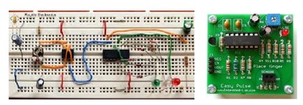
Figure 1 Proof of Concept
-
Schematics Capture
The design Engineer builds the schematics with components chosen in previous stages by means of ECAD tools. Once the schematics are finished, the Design engineer outputs the EBOM, which contains all the information about the components used in the design, and the RIF files, which are the input to the PCB design tool.
Most of the cost and complexity of the design are based on the components and topology used.
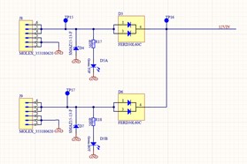
Figure 2 Schematics Capture
-
Printed Circuit Board (PCB) Design
In this phase, the theoretical design becomes real. The Printed Circuit Board (PCB) layout is where the symbols get converted to parts with area and volume. The components and tracks are laid out in the PCB (size, shape, and keep out are driven by the mechanical housing and/or interfaces) following rules for DFM, Design for EMC, DFF, controlled impedance, RF rules, …
Several outputs of the PCB design:
- XY coordinates files to program pick and place machines
- Gerbers and Drill files to build the PCB (graphical information)
- ODB++ to build the PCB and assembly information
3D model of the design to check mechanical interferences.
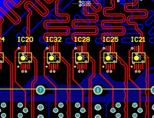
Figure 3 PCB Design Sample
-
Prototype build
Once the design is finished, it must be built to be tested according to the specifications. Here, the engineer makes sure the design fulfills all specifications. If testing is OK, the design is frozen and ready for Qualification Testing.
After all the above is done, it is very important to properly document and store all data with revision control. Not only native data but also the output files.
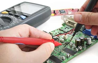
Figure 4 Prototype build and testing
Electronic Design Services in ALTER
In ALTER, as a company with more than 25 years of experience in Electronics Design for highly demanding markets such as Aerospace or Automotive, with robust processes to ensure the designs are done based on the highest quality performance, best in class cost balance, and finished on time.
GET IN TOUCH TODAY!
Do you have questions? Contact us!
Related Posts
- Electronic Assembly Procurement - April 1, 2022
- Prototyping Service - March 31, 2022
- Electronic Design: Technical design capabilities - March 31, 2022





0 comments on Hardware and Software Design