Extreme Temperature Characterization of Passive Components
- Posted by doEEEt Media Group
- On February 12, 2020
- 0
Juan Moreno, Paola Fiadino, Irina Alina Spuma, Juan Barbero & Demetrio López
Alter Technology TÜV NORD S.A.U. Madrid, Spain
Introduction
This article describes the setup developments and some of the results obtained for the temperature characterization from -190ºC to more than +300ºC of passive components normally used for space missions, but with a standard operating temperature range in most of the cases. One of the setups used is based on direct contact with Kelvin probes with a multiplexed solution to allow the characterization up to 150 samples in the same thermal cycle. A second measurements setup is used for measurements at higher temperatures based in not standard soldering and the use of a ceramic custom made climatic chamber door.
Setups for Passive Components Characterization
SETUP 1
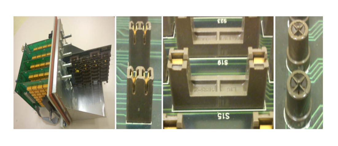
The first measurements setup used by Alter Technology is based in the use of a commutation matrix manufactured by Sun Electronic Systems able to handle up to five component boards. The component boards provide easy Kelvin (4-wires) contact to the component terminals allowing very precise electrical measurements. The use of different component boards allows to measure up to 160 axial or radial components and 80 4-leaded components. The matrix and the different sockets are shown in Fig. 2.
Our company develops labVIEW custom control software for automation and control each type of measurement. The use of the commutation matrix with programmable climatic chambers and custom control software allows performing fully automated measurements at pre-programmed temperature steps. The temperature control is guaranteed by the use of the control thermocouples of the chamber plus several additional thermocouples available to monitor homogeneity of the temperature along the different boards inside the chamber.
This second measurements setup has been developed by Alter Technology in order to overcome some of the limitations presented by the previously explained setup. In this case the contact to the terminals is made with cupper wires ended in golden receptacles. The cupper wires come out of the chamber through a Duratec drilled board. The Duratec material provides good electrical isolation (less than 1nA of leakage current at 250V between consecutive pins) and withstands all the temperature range for which the setup is intended.
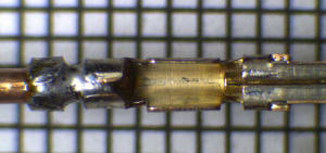
This system removes the 4 amps current limitation at the cost of only allowing semiautomatic measurements. The golden receptacle contacts are welded to the copper wire using a high melting point soldering compound, allowing measurements to up to 300ºC without damaging or even staining the component terminals, like shown in Fig. 3. The measurements are performed through only two wires but the contact resistance added by the setup is lower than 5mΩ. The 4-wire measurement is performed from the other extreme of the copper wires.
Passive Components Characterization Results: Resistance Measurements
The resistance measurements can be performed in a very precise way using the Kelvin sockets. The resistors show a slight increase in the resistance for temperatures below the minimum rated temperature. In some cases, the resistance value obtained falls out of the specification limits for the standard temperature range like shown in Fig. 6. Most of the tested resistors show a very stable behaviour even out of their rated temperature range, an example is shown in Fig. 7, shows in the full report below.
Several measurements have been carried out on thermistors using the same system. The following picture shows the evolution of the resistance of thermistors that are being used to monitor the internal temperature of thermopiles for the REMS (Rover Environmental Monitoring Station) currently aboard the MSL (Mars Science Laboratory) on Mars surface. The resistance evolution and the actual thermocouple can be seen in Fig. 8 and Fig. 9 respectively in the report.
Download or read the full report here
GET IN TOUCH TODAY!
Do you have questions? Contact us!
- Managing EEE components for LEO and lower cost space missions - December 17, 2024
- Filtering Characteristics of Parallel-Connected Fixed Capacitors in LCC-HVDC - November 21, 2024
- ALTER SPACE TEST CENTER: testing approaches for New Space - September 30, 2024


0 comments on Extreme Temperature Characterization of Passive Components