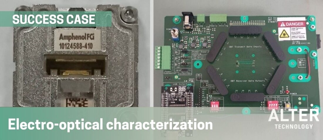
Optical transceiver testing: Electro-optical characterization of 25 GBPS/S
- Posted by Alejandro Rosado Pérez
- On January 24, 2022
- 0
A wide bandwidth test bench has been developed for the optical transceiver testing: electro-optical characterization with different features and bandwidths. The system, which is integrated by a bit-error-rate analyzer, a high-bandwidth oscilloscope, and a pulse pattern generator with a bandwidth up to 28 Gbps/s, was proposed as an excellent candidate for the evaluation of the performance of several optical transceivers.
The electro-optical characterization obtained different intrinsic properties of the signal generated by the transceiver, some of which are shown in this article. A compact device to characterize these devices has facilitated data acquisition and reduced acquisition time.
1. Introduction
Optical transceivers are small photonics devices that transmit and receive information at high transmission rates. These photonics chips are constituted by two differentiated parts: the transmitter, a laser that can be modulated at high speed, and the receiver, a photodiode with broad bandwidth. Optical transceivers can be employed in different fields such as visual terrestrial communications, photonics networks, and sensors in aircraft systems and space applications.
Due to their high capabilities, such components cannot be characterized using conventional measuring equipment, requiring expensive and impractical characterization systems, often consisting of several interconnected pieces of equipment that make optoelectronic measurements difficult.
2. Optical transceiver testing setup
In this case, the optical transceivers that have been employed along all the tests are several 300Gb/s High-Speed Optical Module with 12 Tx and 12 Rx and a bandwidth of 25 Gbps per channel, with very low energy consumption that can be used at distances up to 100m. This device is designed for hi-reliability systems that require operation in harsh environments, including extended temperature ranges. The transceivers were mounted over an evaluation board with 12 input and 12 output RF channels. A general picture of the optical transceiver and its evaluation board is shown in Fig. 1.
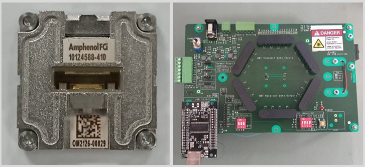
Figure 1. Left: An overview of the optical transceiver, right: the evaluation board
The transceiver can be modulated through the several RF input connectors, two for each module, being able to modulate it using the real and the denied signal provided for the pulse pattern generator. Also, this evaluation board is prepared to obtain the optical signal from all modules of the transceiver through several RF output connectors. In other words, even though the optical transceiver provides an optical signal, the socket in where the devices is mounted translates, through several photodiodes, the optical signal into the electrical domain, so that, all the BER and the eye diagram measurements are performed over an electrical signal, instead of the optical one provided by the transceiver.
The BERTWave MP2110A is an all-in-one instrument with a built-in 2 channel Sampling Oscilloscope and BERT designed for manufacturing inspection of 25G to 800G optical modules.
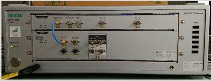
Figure 2. Anritsu MP2110A
This characterization device is constituted by two differentiated parts: a two- channels sampling oscilloscope with an electrical bandwidth of 40 GHz, capable of performing accurate measurements of the eye diagram of the signal and its characteristics, and an up to 28.2 Gbit/s Bit-Error-Rate (BER) tester with an integrated pulse pattern generator that provides electrical pulses at different bit rates (from 9.5 to 28 Gbit/s). The analysis of the signal was performed using the integrated software of the devices that allow obtaining the main characteristics of the resulting eye diagram.
GET IN TOUCH TODAY!
Do you have questions? Contact us!
3. Optical transceiver testing results
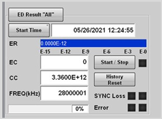
Figure 3. A screenshot with the value of the BER for one channel of an optical transceiver
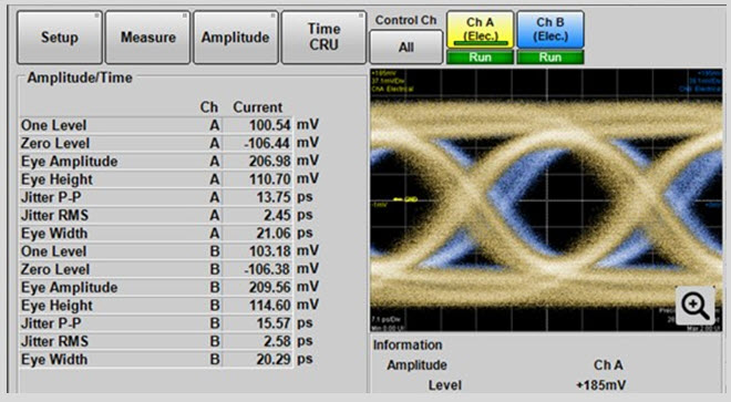
Figure 4. A screenshot with the eye diagram of the generated signal at 28 GHz (right), the values of some quality parameters of the eye diagram
The characterization of the optical transceivers was carried out by analyzing the BER and the main features of the eye diagram of the generated signal in all the channels of each transceiver in different devices. The BER of each transceiver was obtained by modulating them with an RF signal at 28 Gbits/s. Some results of the BER characterization are shown in Fig. 3.
As can be seen in Figure 3, the value of the error ratio of one channel of an optical transceiver is 0e-12 at a modulation rate of 28 GHz. Similar results were found for the eleven other channels of that same transceiver and other transceivers.
Also, using the oscilloscope module of the BERT detector, the eye diagram of the modulated signal can be easily obtained. An example of an eye diagram generated by one of the channels of a transceiver can be seen in the following picture.
At the left part of the screen, the eye diagram of one sample which is modulated at 28 Gbits/s can be observed at two different colors, blue for the generated signal of one channel and yellow for the negative value of this generated signal. At the right part of the figure, some of the key parameters of the signal (eye amplitude, eye height, …) can be seen.
Characterization of each key parameter was performed for all the transceivers, obtaining the following results.
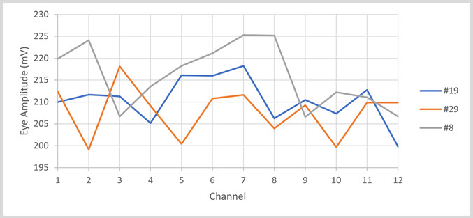
Figure 5. A representation of the eye amplitude for all the channels of one transceiver. Each colour represents different transceivers
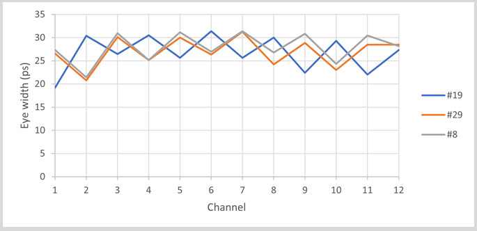
Figure 6. A representation of the eye width for all the channels of one transceiver. Each colour represents different transceivers.
Figures 5 and figure 6 represent the value of the eye amplitude and width, respectively, in terms of each channel of the transceivers and for different transceivers. This characterization was performed for several optical transceivers, obtaining similar values of the key parameters for all their channels.
ALTER Test Expertise
GET IN TOUCH TODAY!
Do you have questions? Contact us!
- Optical transceiver testing: Electro-optical characterization of 25 GBPS/S - January 24, 2022
- Electro-optical characterization of 25 Gbps/s Optical Transceivers - October 8, 2021

0 comments on Optical transceiver testing: Electro-optical characterization of 25 GBPS/S