Power management in Space applications & KEMET KO-CAP® Technology
- Posted by Kemet Electronic Corporation
- On January 4, 2021
- 0
Power management in space applications is related with multiple critical functions as energy storage, conditioning its distribution and conversion from higher to lower levels, feeding all kinds of electronic modules in equipment’s that can be integrated into a launcher (with short duration usage) up to probes or space stations ( with decades of usage).
Power requirements can also be characterized with considerable differences, from few watts needed in CubeSats to several kilowatts and for example in telecommunication spacecraft. While a launcher is supported by electrochemical solutions (batteries), a satellite navigating low or high orbit will collect energy from the sun, transformed by high-efficiency solar cells. Today’s trend is to obtain the highest efficiency, mitigate the power losses, shrinking the module’s volume, boards dimensions or even passive components size. New technologies like Gallium Nitride (GaN) or Silicon Carbide (SiC) are introducing new optimisation opportunities in space applications.
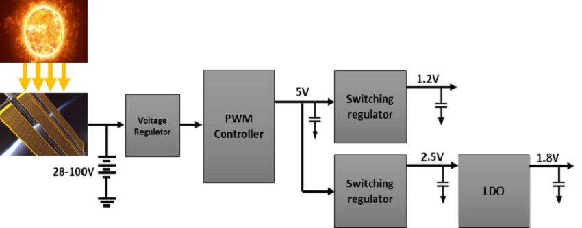
In the next figure, a typical power management configuration is presented. The focus of this blog is to present the critical requirements for the high-efficiency performance of the lowest levels of voltage (1.2V up to 5V) delivered by the PWM controller or, more specifically handled by the power switching regulators where the KEMET KO-CAP® HRA (High-reliability Alternative Series – T541) are the best in class solution considering the typical requirements for this function.

Blog Diagram For Space Applications
Radiation hardened buck converters (as for example, the TPS50601A-SP from Texas Instruments), with a switching frequency range from 100kHz up to 1MHz, can be typically configurated for a standard frequency at 500kHz output for master/slave applications. In this specific scenario, there is a tradeoff between the different switching frequencies. Higher frequencies values may allow the possibility for smaller inductors and output capacitors compared to a power supply that switches at a lower frequency. However, the higher switching frequency may introduce additional losses, which impacts the converter’s efficiency and thermal performance so we may assume a switching frequency of 100 kHz.
The output capacitor characteristics will determine mainly the output ripple voltage and how the regulator will react to a significant variation in the current demand from the load. The capacitor will need to supply the load with the current when the regulator is not fast enough to react and do it, so the capacitor must hold the output voltage above a certain level for a specified amount of time. The output capacitor must be sized to supply the extra current to the load until the control loop responds to the load change. The minimum capacitance is calculated from:

where
- ΔIo is the change in the current requirements,
- fsw is the switching frequency
- ΔVout is the allowable variation the voltage level.
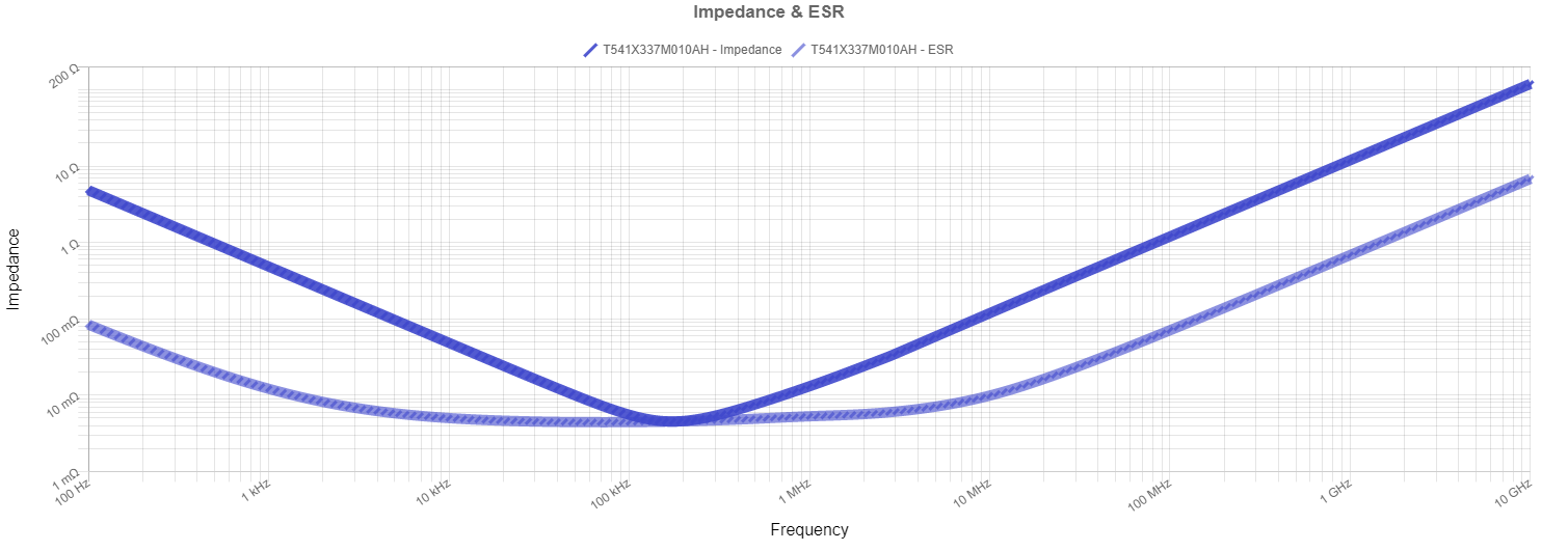
So, for a current demand of 1A and a ΔVout = 0.05×2.5V=0.125V, we arrive to a minimum level of 160uF. The Max ESR (ESR < Vout (ripple) / I ripple) must be lower than 7.5mΩ. In this specific design, a capacitor of 330µF with 6mΩ would be selected. KEMET proposal would be the T541X337M010AHxxxx, with a maximum ESR of 6mΩ and with a costumer code (C-SPEC) that would define the screening level and lot validation data as required by the customer. Additionally, in this case, this capacitor would be DLA approved as per 04052 drawings.

Typical T541X337M010AH Impedance/ESR behaviour over frequency
Source: Kemet Blog
- Decoding The DC-Link - June 8, 2022
- High Reliability: Tantalum Capacitors on the Front Lines of Defense - June 3, 2022
- One Turn Inductors Explained - March 24, 2022

0 comments on Power management in Space applications & KEMET KO-CAP® Technology