AC Line Filters and Insertion Loss Explained
- Posted by doEEEt Media Group
- On October 27, 2020
- 0
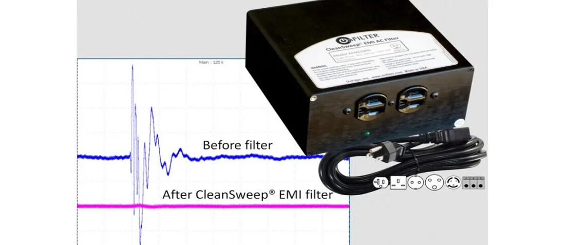
A capacitor is a crucial part of all AC line filters, and much of their performance depends on it. The performance of a capacitor to get rid of unwanted electromagnetic signals is usually referred to as insertion loss. On the following pages, we’ll take a closer look at the questions of electromagnetic noise and insertion loss in electric filters.
AC Line Filters’ Primary Purpose Is to Curb EMI
Electromagnetic interference, also shortened as EMI, is an undesired signal that has a negative impact on the electric circuit performance and can even damage it in some cases. There are interferences with both artificial (man-made) and natural origins.
These possible sources of EMI include lightning and storms, solar flares, motors, radar transmitters, power converters and many other devices, including cell phones (there is even a question of their possible disruption of hospital equipment).
A line filter is a device that is meant to reduce the EMI, allowing other devices in the circuit to function properly.
Though most electronic appliances come equipped with their own noise filters, there are cases in which an external filter has to be introduced – for example in unconventional mains.
How does the Whole Thing Work?
A key part in the performance of a filtering circuit is the configuration of elements that make it up, most notably the inductors and capacitors.
The most basic filter, known as the C filter, is made up of just a one feed-through capacitor. Of course, a performance of such a filter is significantly diminished. By increasing the number of inductors and capacitors and combining them in various configurations, much better performance can be achieved.
Insertion Loss and Its Importance in the Filtering Process
This is one of the chief parameters to take into account when selecting an EMI filter. An insertion loss can be summed up as the ratio of before/after voltage once a filter has been introduced. The insertion loss is given in decibels.
There are many factors influencing the insertion loss, such as electrical configuration, circuit and source impedance, load current, and more. Let’s take a look at some of them at least.
Components Configuration
As mentioned previously, the single elements can reduce the EMI somewhat, but most filters will usually consist of several of them. A one-element filter can achieve a 20 dB insertion loss (in theory), but introducing the second element can almost double this number, not to mention adding more.
Naturally, multiple-element filters are then needed whenever a high performance is required.
Circuit Impedance
The performance of the filter is also influenced by the impedances of the source and load. One must always consider these when thinking about the optimal configuration of capacitive and inductive elements.
Load Current
Will also will have its impact on the filter’s insertion loss, based on the quality and material of the filtering parts. For example, when using ferrite inductors, some insertion loss can occur based on which material is used.
Hopefully, by now you have a better understanding of what the AC filters are, what is EMI, what is insertion loss and some factors that affect it. Feel free to elaborate further on this theme in the comments if you’re a specialist in this field – it will be a welcome addition to this article!
- Managing EEE components for LEO and lower cost space missions - December 17, 2024
- Filtering Characteristics of Parallel-Connected Fixed Capacitors in LCC-HVDC - November 21, 2024
- ALTER SPACE TEST CENTER: testing approaches for New Space - September 30, 2024

0 comments on AC Line Filters and Insertion Loss Explained