Using Cavity Filters for High Precision and Reliability in Narrow Band
- Posted by doEEEt Media Group
- On March 10, 2020
- 0
Using Cavity Filters for High Precision and Reliability in Narrow Band Microwave Applications
Instead of trying to make a broadband microwave filter or bulky waveguide device, a narrow band, low-loss cavity filter can offer users the ability to more accurately look at just the required part of the spectrum of interest.
Many microwave applications, such as repeaters, and electronic warfare equipment, require increased spectral resolution. This means these devices only need to look at a narrow slice of a given band. Filters that are optimized for the whole band, such us planar microstrip devices, are too broadband for these applications. Likewise, traditional high Q filters, such as waveguide devices, are often too large to consider using in these types of applications.
Developing the Perfect Cavity Filter for Your Application
Alongside thin-film microstrip approach to making microwave filters, Knowles Precision Devices also has the expertise to create custom ceramic cavity filters from 6GHz to 67GHz. Based on their decades of experience, RF engineers and material scientists can work directly with clients to fabricate a design for their application, or they can create a design based on predetermined specifications.
In general, ceramic cavity resonator technology can be employed in conjunction with the stable, high Q ceramics developed to create a highly selective, small, low-loss cavity filter. Using a multi-port implementation, a robust filter with wide reject band performance can be delivered without spurious modes. The small, shielded nature of the ceramic filter implementation makes it an ideal choice for integration in low noise receiver front ends with an antenna and pre-amplifier.
Some of the key features of the ceramic cavity filters in typically design include the following:
- Small size – 0.8 x 0.2 x 0.03 inches for a 10 GHz filer
- LO/Multiplier chains/RF pre-select/image filtering
- Low loss in passband: 2-4 dB typical
- Devices scalable from C to Ku band
- Bandwidth 1 to 5 percent
- Narrow footprints are great for switch filter banks
- Surface mount or wire bond capable
- No external shielding required
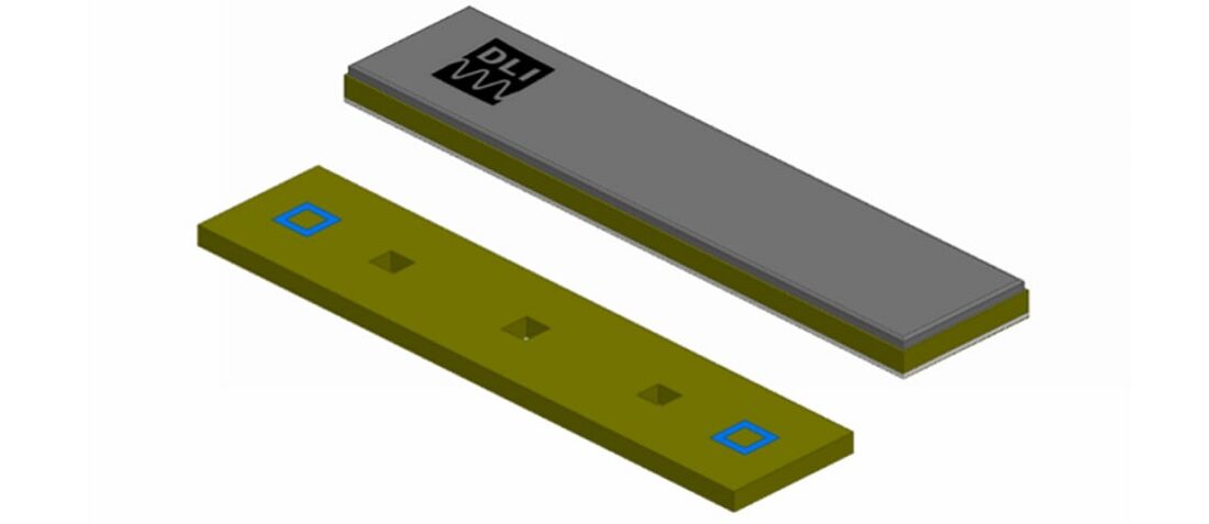
featured image: A basic depiction of a cavity filter; image source: Knowles Precision Devices
- Managing EEE components for LEO and lower cost space missions - December 17, 2024
- Filtering Characteristics of Parallel-Connected Fixed Capacitors in LCC-HVDC - November 21, 2024
- ALTER SPACE TEST CENTER: testing approaches for New Space - September 30, 2024


0 comments on Using Cavity Filters for High Precision and Reliability in Narrow Band