LOW-COST and High-Flexibility SEL Testing Unit
- Posted by Gaizka Eiguren
- On December 3, 2019
- 0
AGENDA
-
- INTRODUCTION
- TESTING UNIT DEVELOPMENT MOTIVATION
- SYSTEM ARCHITECTURE
- SYSTEM SPECIFICATIONS
- SUCCESSFUL EXPERIECES
- CONCLUSIONS
INTRODUCTION
The space industry is changing very fast since the last few years. This industry used to move very slowly towards new technologies that were common in other industries. With the explosion of the information society a lot of new players have come into the space market. Thanks to them, the customers are demanding better specifications and lower prices. This situation is pushing most of the companies to explore new ways of making satellites: when it comes to components, traditional rad-hard parts are progressively been replaced by commercial off-the-shelf (COTS) ones in a lot of applications.
The usage of COTS is only possible after a lot of testing of this parts has been done. As the cost of the testing could increase the cost of the final product, the tests have to be very fast and efficient to prevent this potential problem.
In order to have an excellent time performance in the Single Event Latch up (SEL) tests, a low-cost and high-flexibility testing unit has been developed by Thales Alenia Space Spain called CLARK (Control de Latch up Ajustable y Regulable para Kits de Evaluación).
TESTING UNIT DEVELOPMENT MOTIVATION
- 1st step for COTS selection SEL testing
- Flexibility to be configured for a high range of electronic components
- Maximum quantity in minimum time interval
- Wide range of voltage and temperature conditions
- One single set up (time reducing)
SYSTEM ARCHITECTURE
Setup of each component in a radiation campaign requires a decent amount of time and produce:
- Configuration of its adequate parameters, power supply, etc. for each one can take too long
- Increasing of the cost of the campaign
- Can easily lead to human mistakes when switching between components
Therefore, this system has been designed to allow:
- Testing of as many components as possible
- With one setup
- With automatic switching between devices under test (DUTs)
 With this idea in mind the following design was proposed:
- Control Board: which shall allow the selection of a device at a time and would be in charge of monitoring the currents and telling the system to cut the current if a SEL is detected as well as providing temperature conditions desired for the test
-
- MONITOR the current going through each active channel on the Test Board
- In case of a SEL, command an INTERRUPTION of the power supply
- HEAT UP the DUTs
- Test Board: where all the devices under test would be placed at once which shall go into the vacuum chamber
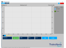
- Graphic User Interface: to command the boards and monitor the test
CONTROL BOARD
- Main task:
-
- DETECT SEL and INTERRUPT the power supply to avoid damaging the devices under test
- Capabilities needed:
- Power supply to the DUTs
- Monitoring currents
- Heat up the DUTs
- Control and coordination of the different parts of the system
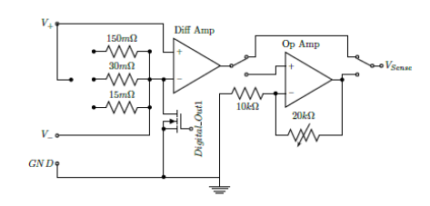
CONTROL BOARD – CURRENT SENSOR WITH DIFFERENTIAL SERIES RESISTOR
- Shunt resistor located in series with the component that is going to be tested
- The current going through the component crosses previously this resistor producing a voltage drop. This shunt resistor has typically a value of a few mΩ. The voltage drop is amplified with a differential amplifier, which produces an output voltage proportional to the current flowing through the shunt resistor.
CONTROL BOARD – POWER SUPPLY
- INTERNAL POWER SUPPLY
- The CLARK System has internal power regulators that will allow to produce a digitally-adjustable output through a microprocessor.
- EXTERNAL POWER SUPPLY
- The system can also be fed with an external voltage source
- A switching matrix acts as an interface between the control board and the test board allows to choose which DUT to feed (one at a time). The DUT selection can be performed through a software with a GUI that controls the microprocessor responsible for the switching.
- In the event of a SEL, the power supply of the device under test has to be cut. To execute this task, a photoMos relay for each DUT is placed in the circuit and will cut down the current if a Latch up is detected in less than 100us
CONTROL BOARD – HEATER CONTROL
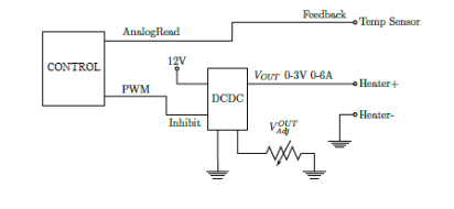
- It has been demonstrated that the SEL cross section has a strong positive linear correlation with the junction temperature. In order to make the developed system capable of performing full SEL Tests, a module that can increase the temperature of the DUT’s junction has been designed.
- The temperature will be raised with a long resistive path placed right on top of the limits of the dice. The temperature is sensed with a NTC resistor and the microprocessor The current flowing through this resistive path will be controlled by a PID control loop performed with the microprocessor.
- If the test is performed outside a vacuum chamber other kind of heat sources could be used such as a heat gun
CONTROL BOARD – CONTROL and COORDINATION
- A single microprocessors takes control of the system by receiving the information from the different modules and commanding the actions to be made.
- When the SEL is detected and the processor commands a cut down of the voltage. It takes some time to open the switches.
- The detection time is the time that will pass from the moment the SEL begins, making the current go up, until the system commands a turn-off of the DUT. With just one device activated at a time, the worst case detection time is 20μs.
 TEST BOARD
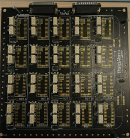
- Max. 18 devices can be placed on this board at a time
- For each lot an independent line brings the power supply to the sample component
- Each line monitored from the control board
- Slots are versatile enough to allow the testing of different basic devices with up to 3 different power rails.
- For more complex components a specific adapter shall be designed to plug into the test board
SYSTEM SPECIFICATION
- With this architecture, the system allows the user to test up to 18 individual components in one run just changing the target of the particles source and switching the power supply. It also allows the test of more complex systems such as Electrical Models boards and Evaluation boards.
- The temperature of the devices, controlled by the CLARK, can be changed individually. The parts can be heated up to 150ºC.
- When it comes to the voltage source, the CLARK has internal voltage regulators that allows to test parts from -30V to 30V. If the voltage range is outside this wide spectrum or if the current required by the part is really high, an external voltage source could be fed to the system in order to perform the tests.
- All this capabilities are controlled through an application running on a PC connected with a USB to the CLARK System.
SUCCESSFUL EXPERIECES
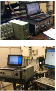 TEST SETUP AT LEUVEN AND TAMU
The proposed system and its previous prototypes have been successfully tested in radiation campaigns at:
- Texas A&M University (TAMU):
- UCL (Lovaina) – Heavy Ion Facility (HIF)
- KVI-CART (University of Groningen)
- GANIL
CONCLUSIONS
Making a flexible and affordable testing unit for SEL should help to increase the number of components that could be tested for campaign. Increasing this number shall also increase the final number of COTS that could potentially be used in space applications and reducing thus the final price of electronic equipment for space.
- LOW-COST and High-Flexibility SEL Testing Unit - December 3, 2019


0 comments on LOW-COST and High-Flexibility SEL Testing Unit