RF Transformer Explained
- Posted by doEEEt Media Group
- On January 11, 2021
- 0
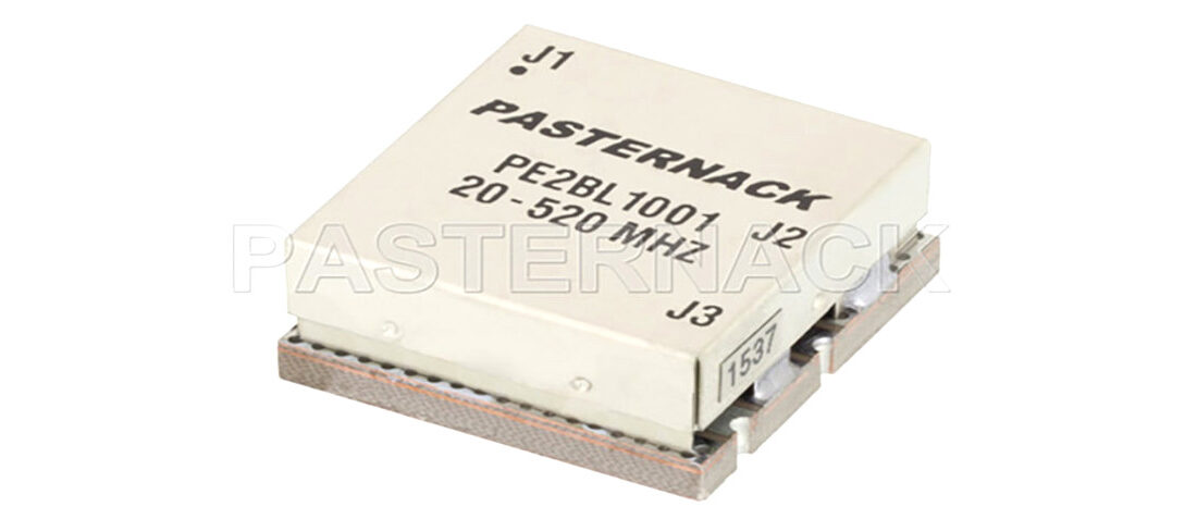
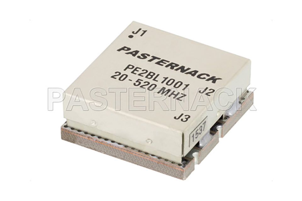
RF Transformers are two, or more, port passive devices with a wide range of uses for many RF applications. One of the most common uses of an RF transformer is the Balun, which provides efficient coupling between unbalanced transmission circuits and balanced circuits. Other common uses are for impedance matching between circuits of different impedances. Other applications include DC isolation, injecting DC current, or enhancing the common mode rejection of a circuit.
RF transformers function via the mechanism of magnetically coupling between conductors structured in such a way to provide the desired function. There are a wide range of RF transformer technologies, including core & wire, transmission line, low temperature co-fired ceramic (LTCC), and monolithic microwave integrated circuit (MMIC), and transformers are built differently depending on the technology. For instance, the original transformer technology was core & wire, where two insulated conductors were wrapped around a ferromagnetic or air core.
With a core & wire transformer, magnetic flux developed within the core by injecting an alternating current through one of the conductive paths results in a current in the secondary path. The ratio of the number of turns around the core determines the extent of the impedance transformation from one side of the transformer to the other. In this case, the performance of the RF transformer is dictated largely by the properties of the core material used. For example, if a ferromagnetic core is used, the core’s magnetic behavior is dependent on the temperature, frequency, and power of signals passing through it. Hence, careful selection of core material and transformer fabrication practices are necessary to realize optimal transformer performance.
Transformers can also be made by wrapping transmission lines around ferromagnetic or air cores. Moreover, quarter-wave lengths of transmission lines can also be used to build another type of this transformer. LTCC and MMIC RF transformers are fabricated using planar conductors and insulative layers to develop very high frequency RF transformers in compact form factors. As the physical size of an this type of transformer greatly influences the RF performance parameters, LTCC and MMIC RF transformers typically exhibit poor low frequency performance compared to physically larger core & wire and transmission line transformers.
Common RF Transformer Applications
- Impedance transformation (i.e. impedance matching)
- Efficiently coupling balanced to unbalanced circuits
- Voltage transformation
- Providing DC isolation between circuits
- Injecting DC current into an RF path
- Enhancing common mode rejection (CMR)
- Ground isolation
- Filtering high frequency signals from a signal line
Source: RF Design article
- Managing EEE components for LEO and lower cost space missions - December 17, 2024
- Filtering Characteristics of Parallel-Connected Fixed Capacitors in LCC-HVDC - November 21, 2024
- ALTER SPACE TEST CENTER: testing approaches for New Space - September 30, 2024


0 comments on RF Transformer Explained